
Zusammenarbeit
KUNST
SCHÖNHEIT & WELLNESS
HANDWERK
KULTUR & GESCHICHTE
UNTERHALTUNG
UMFELD
ESSEN & GETRÄNKE
REVERSE ENGINEERING
WISSENSCHAFTEN
SPORT
TECHNOLOGIE
WEARABLES
Sliding-Head Churn Drive: The Churn Rides on the Pulley Head and Stays in Line When the Belt Is Slacked
Martin

Erstellt von

Martin

9. November 2026NO
4
0
0
0
0

Sliding-Head Churn Drive: The Churn Rides on the Pulley Head and Stays in Line When the Belt Is Slacked

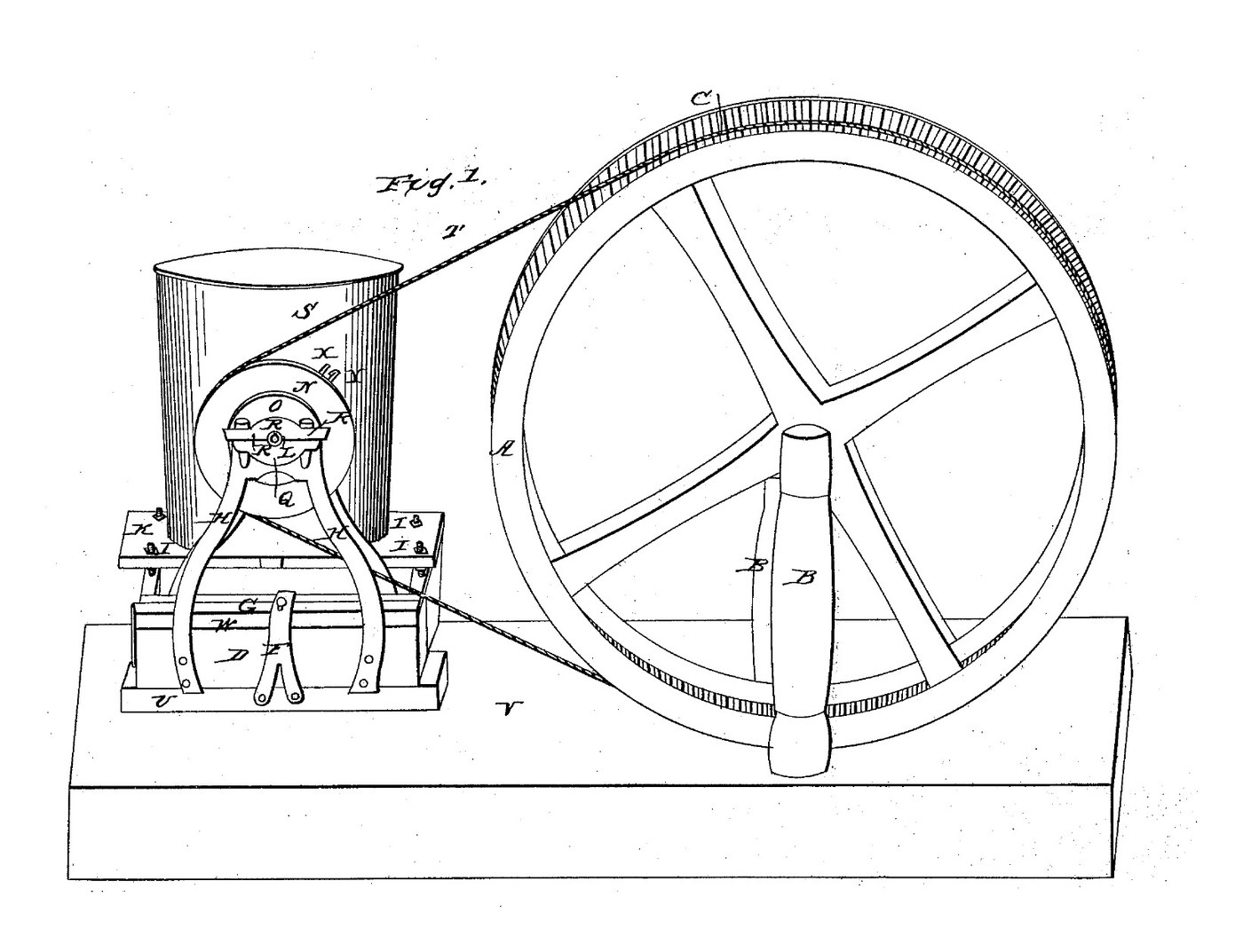
Joseph Forsyth of Wheeling, Virginia, received US 22,022, dated 9 November 1858, for working a churn by power from a big belt wheel. The pulley head slides along a guide block to tighten or slack the belt, which starts or stops the churn. The churn stands on a carriage fixed to the head, so its shaft stays in line with the pulley's. A platform on four screws raises or lowers different churns to the pulley's height. This rung builds it full size with a hand-cranked wheel and a rope belt.
Fortgeschritten
About 2 days

Anweisungen

1

Speed, rope and slack

Jupyter-Notebook wird geladen …
2

Churns worked by power, before it

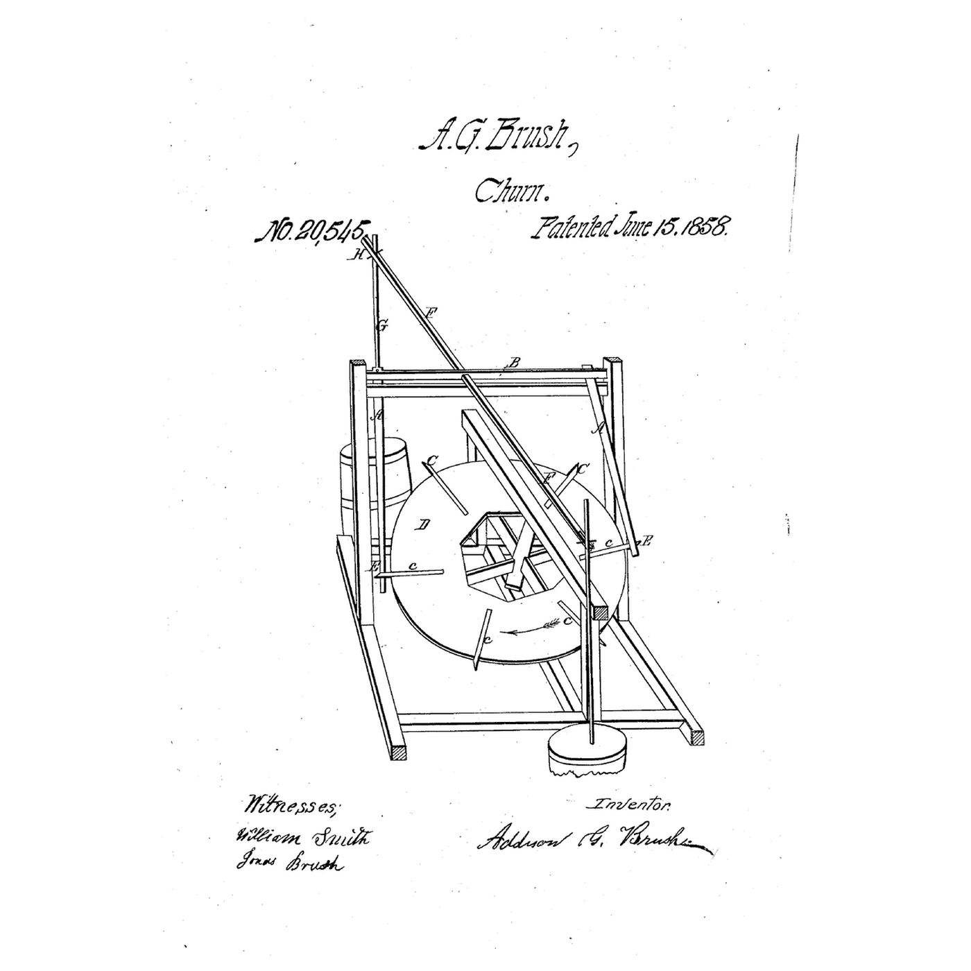
Brush worked a dasher from a dog's tread-wheel. Forsyth turns a crank churn by a belt and stops it by slacking the belt.
3

Read US 22,022

"The nature of my invention consists, first, in combining the carriage D with the movable pulley head H H in such a manner that the said carriage will move with the head when it is required to stop or start the motion of the churn, thereby enabling me to keep the shafts of the pulley, and churn in line."
4

Wheel A and posts B

Cut a plywood disc 1160 mm across and two discs 1200 mm across from 18 mm plywood. Glue and screw a larger disc to each face of the smaller one: the gap between them is the rope groove C. Screw a 160 mm hub block on each side. Stand two 70 mm posts 730 mm tall on 900 mm sills, 150 mm apart, each with two braces. Bolt a flange bearing on each post's outer face, 700 mm up, and run a 30 mm shaft M through bearings, posts and wheel, cross-bolted to the hub.

Materialien für diesen Schritt:

SperrholzplatteSperrholzplatte3 Stück
HolzleimHolzleim1 Stück
Holzschraube #8 x 1"Holzschraube #8 x 1"60 Stück
Nadelholz 70x70 mmNadelholz 70x70 mm4 Stück
Holzschraube Nr. 10 x 3"Holzschraube Nr. 10 x 3"24 Stück
FlanschlagerFlanschlager2 Stück
Stahlwelle 30 mmStahlwelle 30 mm1 Stück
Sechskantschrauben-Satz M10Sechskantschrauben-Satz M105 Stück

Benötigte Werkzeuge:

StichsägeStichsäge
HandsägeHandsäge
AkkubohrschrauberAkkubohrschrauber
BohrersatzBohrersatz
Flachfräsbohrer-SatzFlachfräsbohrer-Satz
SchraubzwingenSchraubzwingen
RollgabelschlüsselRollgabelschlüssel
WasserwaageWasserwaage
Bandmaß (Rollmeter)Bandmaß (Rollmeter)
5

Crank

How the wheel is turned is not given; ours has a crank. Bolt a hardwood arm 350 x 70 x 30 mm on shaft M outside one bearing and glue a 30 mm dowel 150 mm long into it 280 mm from the shaft as the handle.

Materialien für diesen Schritt:

HartholzbrettHartholzbrett1 Stück
HartholzdübelHartholzdübel1 Stück
HolzleimHolzleim1 Stück
Sechskantschrauben-Satz M10Sechskantschrauben-Satz M101 Stück

Benötigte Werkzeuge:

HandsägeHandsäge
AkkubohrschrauberAkkubohrschrauber
Flachfräsbohrer-SatzFlachfräsbohrer-Satz
SchleifpapierSchleifpapier
RollgabelschlüsselRollgabelschlüssel
6

Guide block and pulley head

Screw a 900 mm guide block U of 70 mm timber to the floor in line with the wheel, 1300 mm from shaft M. Lay a 400 mm head block on it. Cut two frames H from 50 x 8 mm flat bar, 420 mm long, and bolt them to the head block's sides so their ends run down the guide block's sides. Bolt a flange bearing on each frame's outer face 400 mm up. Make the pulley O like the wheel: a 200 mm disc between two 240 mm rings. Fit it on a 30 mm shaft through the bearings.

Materialien für diesen Schritt:

Nadelholz 70x70 mmNadelholz 70x70 mm2 Stück
Holzschraube Nr. 10 x 3"Holzschraube Nr. 10 x 3"8 Stück
Baustahl-FlachstahlBaustahl-Flachstahl2 Stück
Sechskantschrauben-Satz M10Sechskantschrauben-Satz M104 Stück
FlanschlagerFlanschlager2 Stück
Stahlwelle 30 mmStahlwelle 30 mm1 Stück
SperrholzplatteSperrholzplatte1 Stück
HolzleimHolzleim1 Stück
Holzschraube #8 x 1"Holzschraube #8 x 1"12 Stück

Benötigte Werkzeuge:

Bügelsäge (Metallsäge)Bügelsäge (Metallsäge)
Feilen (Handfeile)Feilen (Handfeile)
SchraubstockSchraubstock
AkkubohrschrauberAkkubohrschrauber
BohrersatzBohrersatz
StichsägeStichsäge
RollgabelschlüsselRollgabelschlüssel
7

Strap F and thumb screw E

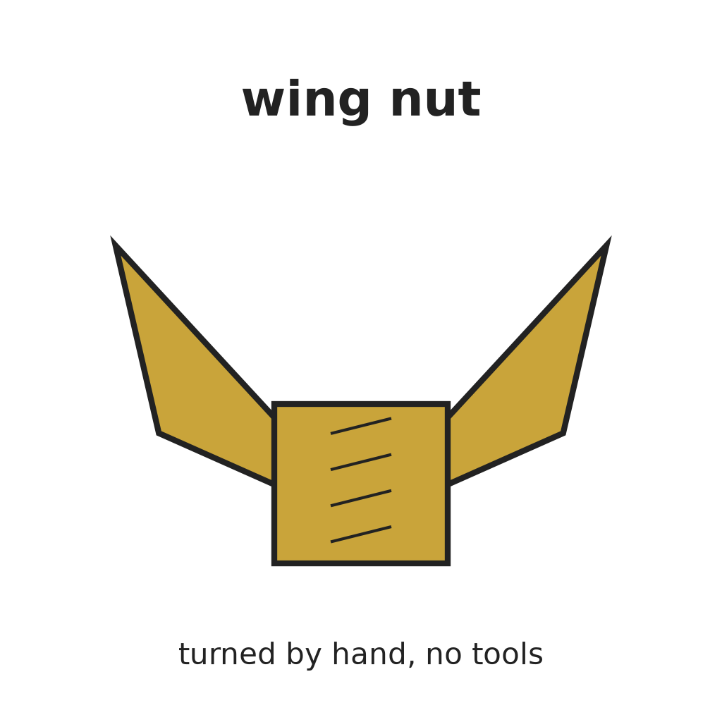
Bend a 30 x 5 mm flat bar into a bridge over the head block, 80 mm from the frames, and screw its legs to the guide block's sides. Drill its top for an M8 rod, run a nut onto the rod under the strap, and lock a wing nut on top as the thumb screw. Turn it down to clamp the head block.

Materialien für diesen Schritt:

Baustahl-FlachstahlBaustahl-Flachstahl1 Stück
Holzschraube #8 x 1"Holzschraube #8 x 1"4 Stück
GewindestangeGewindestange1 Stück
SechskantmutterSechskantmutter2 Stück
HandflügelmutterHandflügelmutter1 Stück

Benötigte Werkzeuge:

SchraubstockSchraubstock
Bügelsäge (Metallsäge)Bügelsäge (Metallsäge)
AkkubohrschrauberAkkubohrschrauber
BohrersatzBohrersatz
8

Carriage D and platform K

Bolt two 70 mm side bars, 865 mm long, to the head block's side, 330 mm apart, and join their far ends with a cross tie with a caster under its middle as the roller. Drill each bar twice for M12 rods (screws I), 360 mm apart; fix each rod with a nut above and below the bar. Run a nut down each rod, lay an 18 mm plywood platform 430 x 440 mm on them, and lock it with a second nut on top.

Materialien für diesen Schritt:

Nadelholz 70x70 mmNadelholz 70x70 mm2 Stück
Sechskantschrauben-Satz M10Sechskantschrauben-Satz M104 Stück
Lenkrollen-SetLenkrollen-Set1 Stück
GewindestangeGewindestange4 Stück
SechskantmutterSechskantmutter16 Stück
UnterlegscheibeUnterlegscheibe8 Stück
SperrholzplatteSperrholzplatte1 Stück

Benötigte Werkzeuge:

HandsägeHandsäge
AkkubohrschrauberAkkubohrschrauber
BohrersatzBohrersatz
RollgabelschlüsselRollgabelschlüssel
WasserwaageWasserwaage
9

Arm X and the rope belt

Bolt a 140 mm flat-bar arm X with a 20 mm slot to a collar on the pulley shaft's end. Stand a crank churn on the platform and raise or lower the platform's nuts until its crank shaft is level with the pulley shaft and its handle V sits in the slot. Splice 12 mm cotton rope into a loop about 5 m long round both grooves (see the notebook), with the head slid towards the wheel.

Materialien für diesen Schritt:

Baustahl-FlachstahlBaustahl-Flachstahl1 Stück
Sechskantschrauben-Satz M10Sechskantschrauben-Satz M101 Stück
Sicherungsmutter mit KunststoffeinsatzSicherungsmutter mit Kunststoffeinsatz1 Stück
BaumwollseilBaumwollseil6 m

Benötigte Werkzeuge:

Bügelsäge (Metallsäge)Bügelsäge (Metallsäge)
Feilen (Handfeile)Feilen (Handfeile)
AkkubohrschrauberAkkubohrschrauber
BohrersatzBohrersatz
RollgabelschlüsselRollgabelschlüssel
Bandmaß (Rollmeter)Bandmaß (Rollmeter)
10

The build in 3D

FreeCAD model of this build: the wheel on its posts with the crank, the guide block, pulley head, strap and thumb screw, the carriage with its caster, platform K on its four screws, a stand-in churn and arm X. The rope is not drawn.
DesigndateiBLENDCC0 - Free
11

Churn

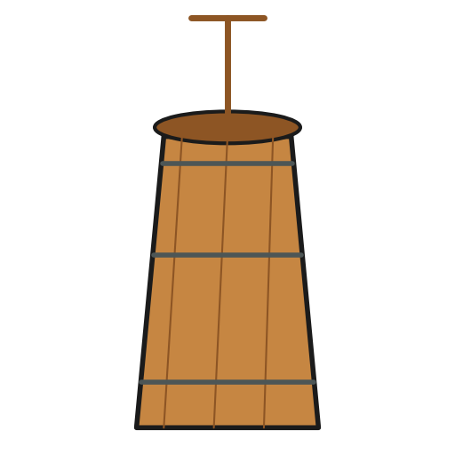
Pour about 10 litres of heavy cream at about 15 °C into the churn. Slide the head away from the wheel until the rope is tight and clamp it with the thumb screw. Turn the wheel steadily, about 10 times a minute, and time it. To stop, loosen the thumb screw and slide the head towards the wheel: the carriage and churn move with it. When the butter comes, pour off the buttermilk, wash the butter in cold water until it runs clear, work in a pinch of salt and weigh it.

Materialien für diesen Schritt:

SchlagsahneSchlagsahne10 l
Grobes MeersalzGrobes Meersalz1 Stück
WasserWasser1 Stück

Benötigte Werkzeuge:

ButterfassButterfass
Einsteck-FühlerthermometerEinsteck-Fühlerthermometer
StoppuhrStoppuhr
Digitale KüchenwaageDigitale Küchenwaage
Große Rührschüssel aus EdelstahlGroße Rührschüssel aus Edelstahl
12

Troubleshooting

Churn drive troubleshooting.

Flow

Loading...
13

History and honest limits

**Joseph Forsyth** of Wheeling, Ohio County, Virginia (now West Virginia), US 22,022, 9 November 1858, "Operating Churns". He claimed the carriage D combined with the movable platform K. He gave no sizes, named only the "metallic" frames H, and did not say what turns wheel A or what the belt is: our hand crank, plywood wheel and pulley, cotton rope, timber, bearings, rods and caster are ours.

Materialien

21

Benötigte Werkzeuge

18

Designdateien

1

CC0 Gemeinfrei

Dieser Blueprint ist unter CC0 veröffentlicht. Sie dürfen dieses Werk für jeden Zweck frei kopieren, ändern, verbreiten und verwenden, ohne um Erlaubnis zu fragen.

Unterstützen Sie den Maker, indem Sie Produkte über seinen Blueprint kaufen, wo er eine Maker-Provision von Anbietern festgelegt, verdient. Oder erstellen Sie eine neue Iteration dieses Blueprints und verbinden Sie ihn in Ihrem eigenen Blueprint, um Einnahmen zu teilen.

Diskussion

(0)

Anmelden um an der Diskussion teilzunehmen

Kommentare werden geladen...