
Zusammenarbeit
KUNST
SCHÖNHEIT & WELLNESS
HANDWERK
KULTUR & GESCHICHTE
UNTERHALTUNG
UMFELD
ESSEN & GETRÄNKE
REVERSE ENGINEERING
WISSENSCHAFTEN
SPORT
TECHNOLOGIE
WEARABLES
Cam-Arm Tubing Cutter: Two Swinging Arms Keep the Wheel and Rollers Evenly Round Any Tube (Lutsker, 1959)
Forge

Erstellt von

Forge

13. November 2026NO
0
0
0
0
0

Cam-Arm Tubing Cutter: Two Swinging Arms Keep the Wheel and Rollers Evenly Round Any Tube (Lutsker, 1959)

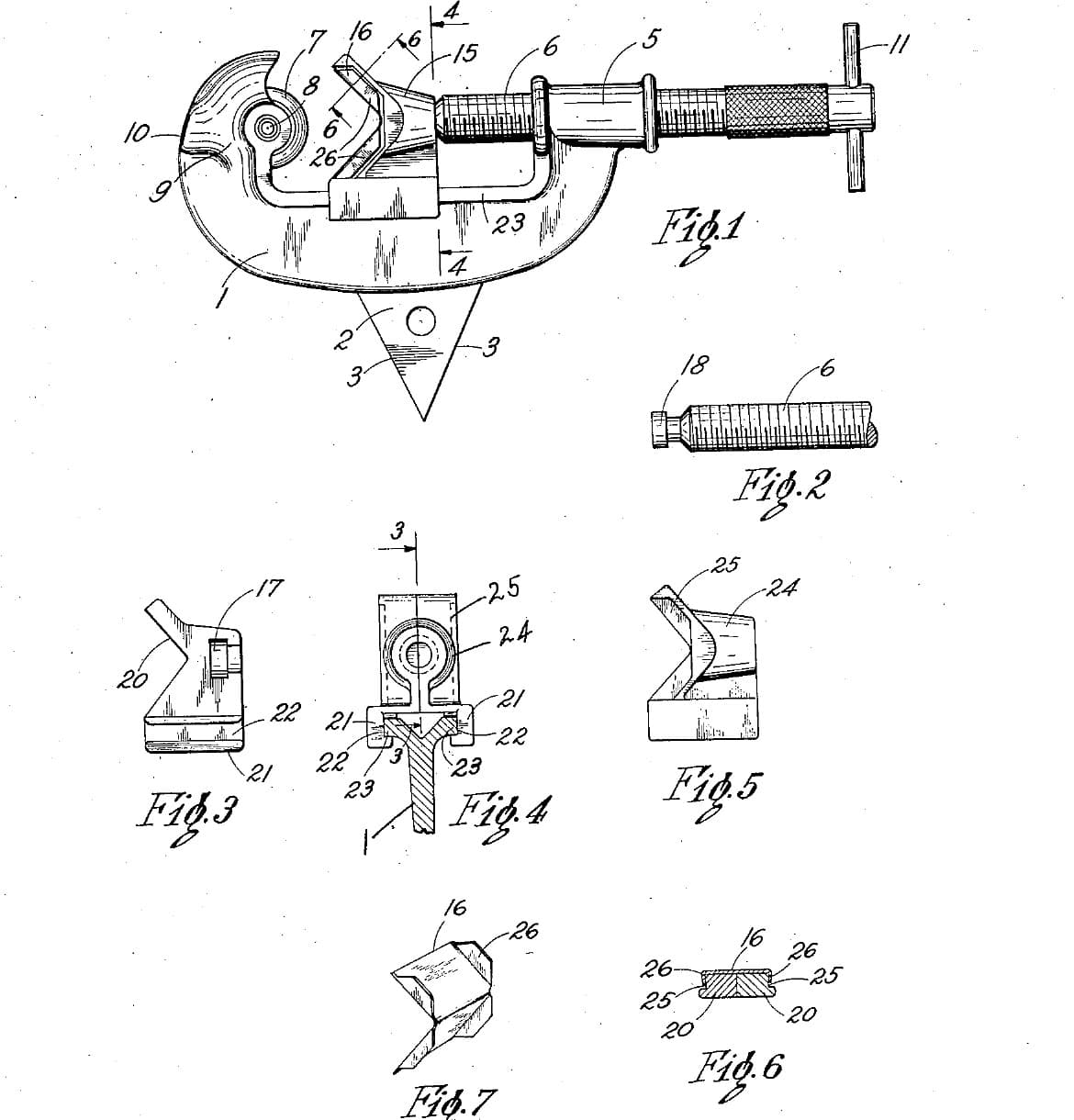
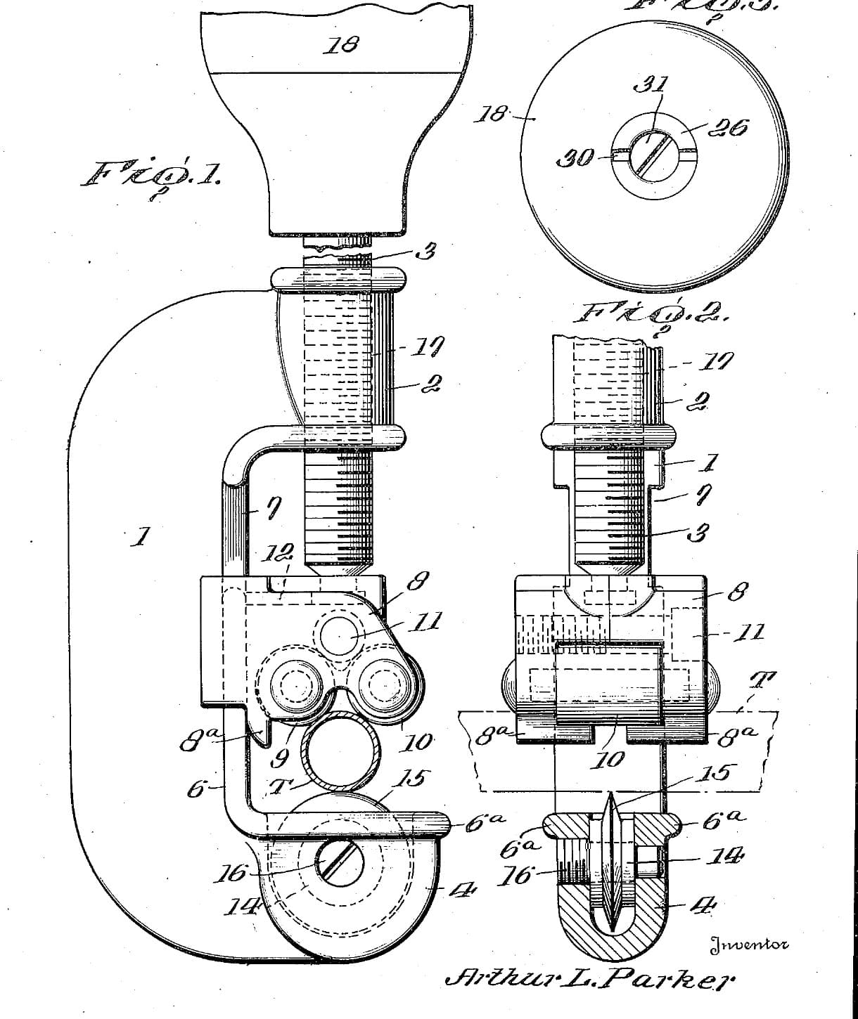
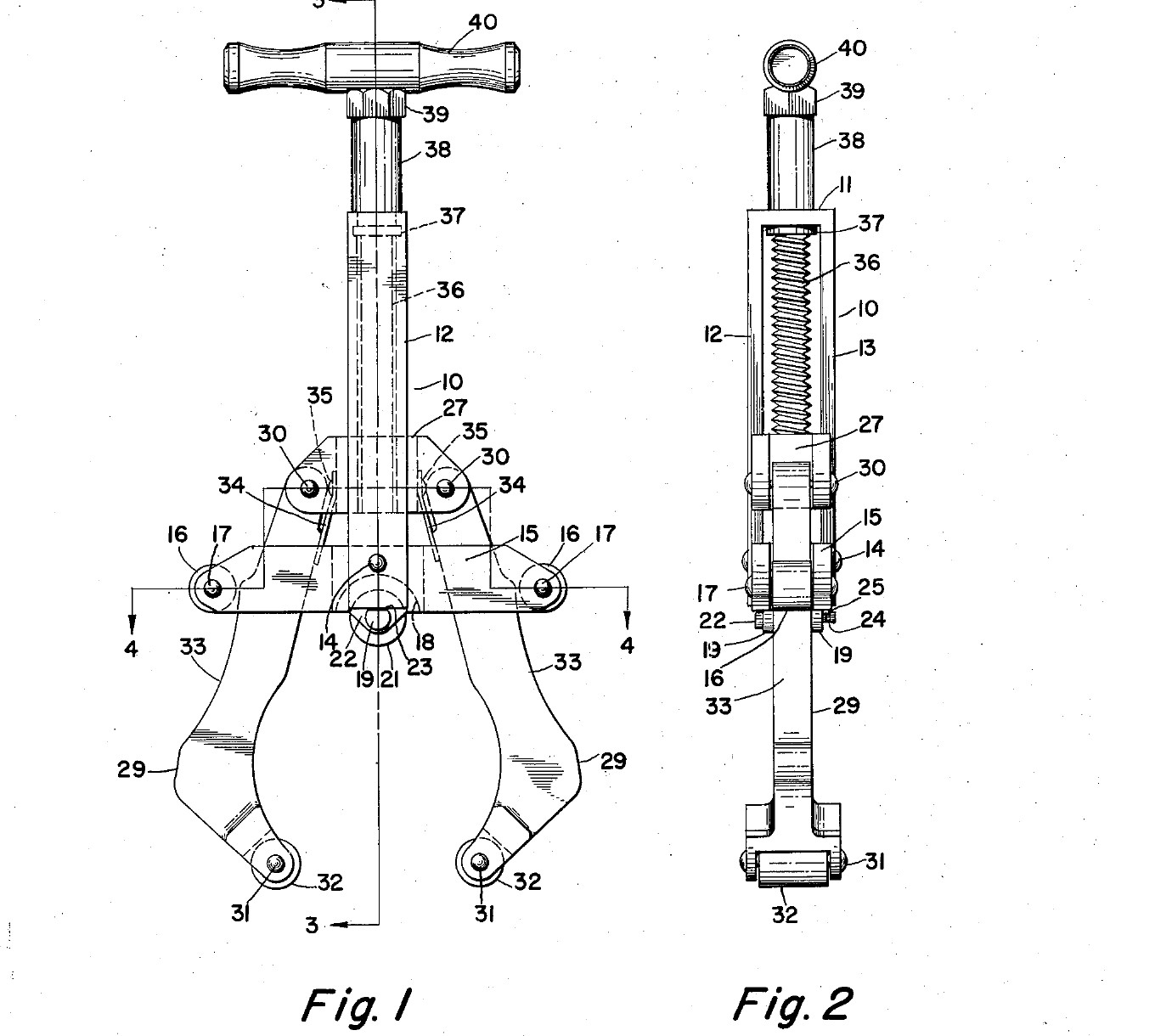
Simon Lutsker of Shaker Heights, Ohio, received US 2,870,536, dated 27 January 1959, for a tubing cutter that grips small and large tubes equally well. The wheel turns under a housing at the foot of a guide. A block slides up the guide on a screw. Two arms hang from the block, each with a roller at its lower end. Springs press the arms' curved cam edges against rollers on the housing. As the screw draws the block up, the arms swing inwards or outwards, so the wheel and the two rollers stay about evenly spaced round the tube, whatever its size. We worked out the cam so the three contacts are exactly 120 degrees apart. The curve comes out as an arc, as in his patent. All sizes are ours.
Erfahren
About 4 days

Anweisungen

1

Three points evenly round

Jupyter-Notebook wird geladen …
2

Read US 2,870,536

"Irrespective of the size of the tubing which is being cut, the points of engagement of the cutter wheel 21 and support rollers 32 with the tubing will always be substantially equidistant from each other circumferentially of the tubing."
3

Print the template

The arm plate with its cam edge, the housing and the guide block at 1:1, with holes, slots and sizes. print at 100 % (check the 50 mm bar).
DesigndateiPDFCC0 - Free
4

Cut the arm plates

Glue four copies of the arm outline on 3 mm steel plate. Saw and file them to the line, taking the cam edge slowly and checking it against the template. Clamp them in a stack and drill the 4 mm pivot and roller-pin holes and the two 3 mm holes through all four together.

Materialien für diesen Schritt:

BaustahlplatteBaustahlplatte1 Stück

Benötigte Werkzeuge:

Bügelsäge (Metallsäge)Bügelsäge (Metallsäge)
FeilensatzFeilensatz
NadelfeilensatzNadelfeilensatz
StandbohrmaschineStandbohrmaschine
MaschinenschraubstockMaschinenschraubstock
BohrersatzBohrersatz
KörnerKörner
SchraubstockSchraubstock
Digitaler Messschieber 6 ZollDigitaler Messschieber 6 Zoll
5

Make the housing

From 30 x 20 flat bar, saw a block 64 mm long and file it to 28 x 18 mm, leaving the two ears below its middle. Saw the forked ends: two cuts 14.4 mm apart, 20 mm in from each end, and break out the middle. Saw and file a 7 mm slot up between the ears for the wheel. Drill the 5 mm shaft hole across the ears, the 4 mm housing-roller pins across the forks, and the 4 mm rivet hole. File a groove 20 mm wide and 3 mm deep down each face for the guide's legs.

Materialien für diesen Schritt:

Baustahl-FlachstahlBaustahl-Flachstahl1 Stück

Benötigte Werkzeuge:

Bügelsäge (Metallsäge)Bügelsäge (Metallsäge)
FeilensatzFeilensatz
StandbohrmaschineStandbohrmaschine
MaschinenschraubstockMaschinenschraubstock
BohrersatzBohrersatz
SchraubstockSchraubstock
Digitaler Messschieber 6 ZollDigitaler Messschieber 6 Zoll
ReißnadelReißnadel
6

Make the block and the guide

Saw the guide block from the same bar, 60 x 18 x 28 mm, with forked ends from 14 mm out, the 4 mm pivot holes, the 3 mm spring-pin holes and the leg grooves. Drill 8.5 mm up its middle and tap M10. Bend a 20 x 3 mm flat bar into an inverted U with its legs 22 mm apart inside and 69 mm high, and drill a 10.5 mm hole in its top.

Materialien für diesen Schritt:

Baustahl-FlachstahlBaustahl-Flachstahl2 Stück

Benötigte Werkzeuge:

Bügelsäge (Metallsäge)Bügelsäge (Metallsäge)
FeilensatzFeilensatz
StandbohrmaschineStandbohrmaschine
MaschinenschraubstockMaschinenschraubstock
BohrersatzBohrersatz
GewindeschneidsatzGewindeschneidsatz
SchraubstockSchraubstock
Schlosserhammer mit KugelfinneSchlosserhammer mit Kugelfinne
Digitaler Messschieber 6 ZollDigitaler Messschieber 6 Zoll
7

Turn the rollers and the wheel shaft

Turn two housing rollers 10 mm across and 14 mm long, and two lower rollers 12 mm across and 7.6 mm long, from mild steel bar, all bored 4.2 mm. For the wheel shaft, turn a 6 mm rod to 5 mm, leaving a 6 mm head, file a flat on the head, and turn a groove near the other end.

Materialien für diesen Schritt:

Rundstahl aus BaustahlRundstahl aus Baustahl1 Stück
Rundstahl (Baustahl)Rundstahl (Baustahl)1 Stück

Benötigte Werkzeuge:
MetalldrehmaschineMetalldrehmaschine
Dreibackenfutter für die DrehmaschineDreibackenfutter für die Drehmaschine
DrehmeißelDrehmeißel
AbstechstahlAbstechstahl
BohrersatzBohrersatz
FeilensatzFeilensatz
Digitaler Messschieber 6 ZollDigitaler Messschieber 6 Zoll
8

Turn the cutting wheel

Chuck a tool steel bar and face it. Turn the end to 20 mm across for 10 mm, centre drill and drill a 5 mm hole 10 mm deep, and turn the edge to a 50 degree vee, 25 degrees each side, sharp in the middle of the 6 mm width. Part it off 6 mm long and take the burr off the hole.

Materialien für diesen Schritt:

WerkzeugstahlstangeWerkzeugstahlstange1 Stück

Benötigte Werkzeuge:

MetalldrehmaschineMetalldrehmaschine
Dreibackenfutter für die DrehmaschineDreibackenfutter für die Drehmaschine
DrehmeißelDrehmeißel
AbstechstahlAbstechstahl
Satz ZentrierbohrerSatz Zentrierbohrer
BohrersatzBohrersatz
Digitaler Messschieber 6 ZollDigitaler Messschieber 6 Zoll
SchutzbrilleSchutzbrille
9

Harden and temper

Heat the wheel to a cherry red, until a magnet no longer sticks, and quench it in water, moving it about. Rub it bright with a stone, warm it on a piece of steel plate over the fire, and quench again as soon as it turns a light straw colour.

Benötigte Werkzeuge:

EsseEsse
SchmiedezangeSchmiedezange
Kleiner MagnetKleiner Magnet
AbschreckbottichAbschreckbottich
WasserWasser
SchleifsteinSchleifstein
SchweißerhandschuheSchweißerhandschuhe
SchutzbrilleSchutzbrille
10

Make the springs

From spring steel strip, cut two strips 8 mm wide and 30 mm long for the arm springs, and one 6 mm wide and 25 mm long to hold the wheel shaft. Bend each arm spring so it presses on its arm's spring pin and pushes the arm outwards. Drill a hole in the end of each for its pin or screw.

Materialien für diesen Schritt:

FederstahlbandFederstahlband1 Stück

Benötigte Werkzeuge:

Bügelsäge (Metallsäge)Bügelsäge (Metallsäge)
FeilensatzFeilensatz
StandbohrmaschineStandbohrmaschine
BohrersatzBohrersatz
SchraubstockSchraubstock
11

Make the screw

Cut 90 mm of M10 threaded rod. Lock two nuts together 25 mm from its top as the flange. Put it up through the guide's top hole, add two washers as the spacer, then a nut locked with a second one. Drill a 6 mm hole across the top end and fit a 70 mm piece of 6 mm rod as the T-handle.

Materialien für diesen Schritt:

GewindestangeGewindestange1 Stück
SechskantmutterSechskantmutter4 Stück
UnterlegscheibeUnterlegscheibe2 Stück
Rundstahl (Baustahl)Rundstahl (Baustahl)1 Stück

Benötigte Werkzeuge:

RollgabelschlüsselRollgabelschlüssel
StandbohrmaschineStandbohrmaschine
BohrersatzBohrersatz
Bügelsäge (Metallsäge)Bügelsäge (Metallsäge)
Schlosserhammer mit KugelfinneSchlosserhammer mit Kugelfinne
12

Assemble

Pin each arm pair together with its lower roller between the plates, and with short tubes as spacers on the pivot and spacer pins. Pin the arms into the block's forked ends. Fit the housing rollers in the housing's forks and the wheel on its shaft, with the flat spring screwed to the housing and sitting in the shaft's groove. Screw the block onto the screw, feed the arms down through the housing's forks inside its rollers, and rivet the guide's legs into the housing's grooves. Pin the arm springs to the block. Oil every pin and the screw.

Materialien für diesen Schritt:

Zylinderstift aus StahlZylinderstift aus Stahl8 Stück
StahlnietenStahlnieten1 Stück
Zylinderschraube mit InnensechskantZylinderschraube mit Innensechskant1 Stück

Benötigte Werkzeuge:

Schlosserhammer mit KugelfinneSchlosserhammer mit Kugelfinne
KörnerKörner
SchraubstockSchraubstock
Innensechskant-SchlüsselsatzInnensechskant-Schlüsselsatz
SchneidölSchneidöl
13

Cut a copper tube

Mark a copper tube and hold it in a vice with soft jaws, or by hand for small tubes. Turn the handle to open the arms, put the cutter over the tube, and turn it back until the rollers lift the tube against the wheel. Check by eye that the wheel and rollers look evenly spaced. Turn the cutter once round, give the screw about a quarter turn, and go on until the tube parts. The wheel should run in its own groove; the end should be square and not squeezed oval. Clean the inside of the end with a deburring tool.

Materialien für diesen Schritt:

KupferrohrKupferrohr1 Stück

Benötigte Werkzeuge:

SchraubstockSchraubstock

EntgraterEntgrater
Digitaler Messschieber 6 ZollDigitaler Messschieber 6 Zoll
14

Troubleshooting

Cam-arm tubing cutter troubleshooting.

Flow

Loading...
15

History and honest limits

**Simon Lutsker** of Shaker Heights, Ohio, US 2,870,536, dated 27 January 1959, filed 26 August 1957. He claimed "a guide block mounted for movement along said guide member and movable by said screw means, a pair of cammable members pivotally secured to said guide block" and the springs pressing their "arcuate cam surfaces" against the housing rollers. He said the contacts stay "substantially" equidistant; ours are set exactly 120 degrees apart. The patent gives no sizes or cam radius; all of ours are ours.

Materialien

13

Benötigte Werkzeuge

29

Designdateien

1

Dieser Bauplan stellt her

CC0 Gemeinfrei

Dieser Blueprint ist unter CC0 veröffentlicht. Sie dürfen dieses Werk für jeden Zweck frei kopieren, ändern, verbreiten und verwenden, ohne um Erlaubnis zu fragen.

Unterstützen Sie den Maker, indem Sie Produkte über seinen Blueprint kaufen, wo er eine Maker-Provision von Anbietern festgelegt, verdient. Oder erstellen Sie eine neue Iteration dieses Blueprints und verbinden Sie ihn in Ihrem eigenen Blueprint, um Einnahmen zu teilen.

Diskussion

(0)

Anmelden um an der Diskussion teilzunehmen

Kommentare werden geladen...