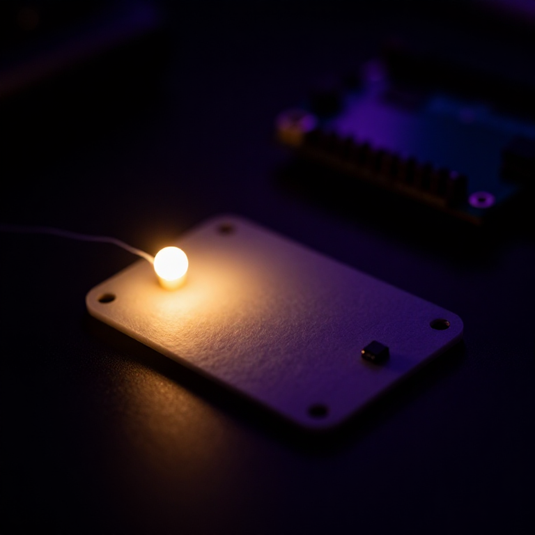


Making a LilyPad Night-Light
Give your fabric a sense of sight. A LilyPad light sensor tells the microcontroller how bright the room is, and a short program switches an LED on when it gets dark. Sew it into a bag, a hat or a bedside patch for a soft glow that only appears at night — your first sensor-driven wearable.
Anweisungen
Sew the board, sensor and LED
Sew the board, sensor and LED
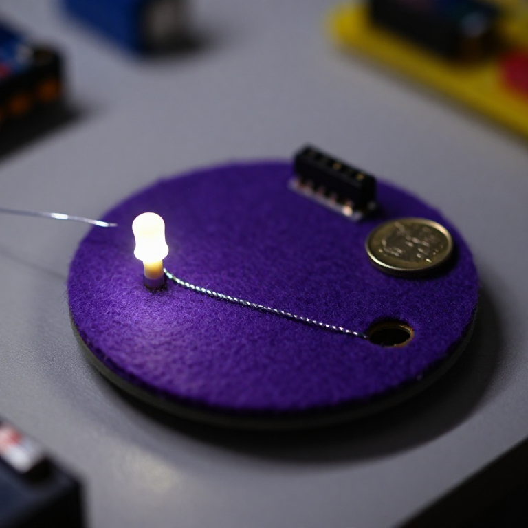
Sew a LilyPad Arduino, a LilyPad light sensor and a LilyPad LED onto felt. Wire it: the LED's + tab to pin 5 and its - tab to -; the sensor's + tab to the board's +, its - tab to -, and its signal (S) tab to analog pin A2. Keep the power (+), ground (-) and signal lines from crossing anywhere.
Materialien für diesen Schritt:
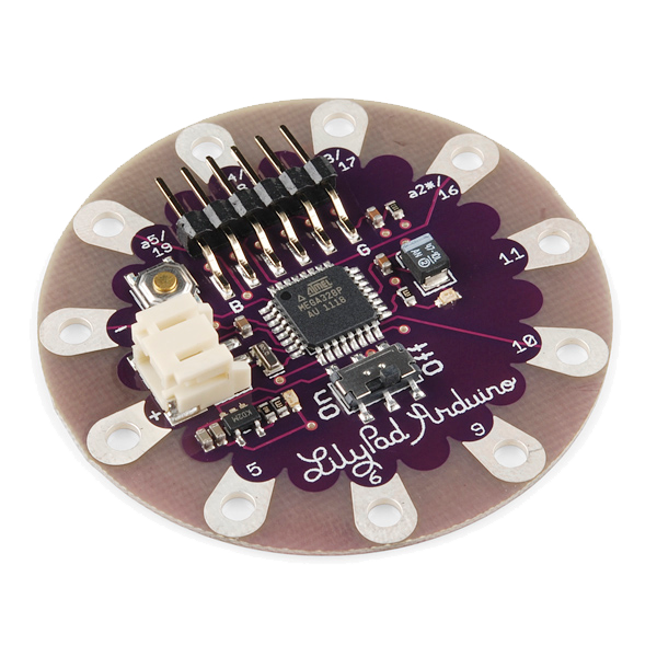 LilyPad Arduino Simple Board1 Stück
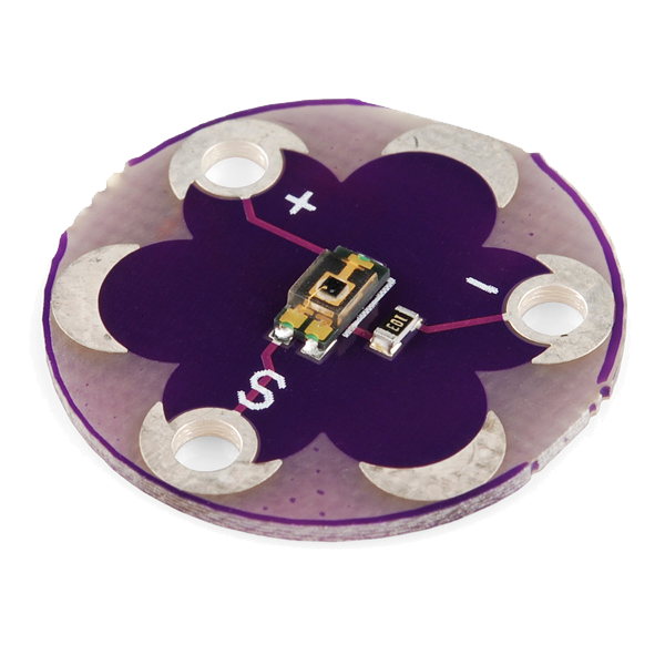 LilyPad Light Sensor1 Stück
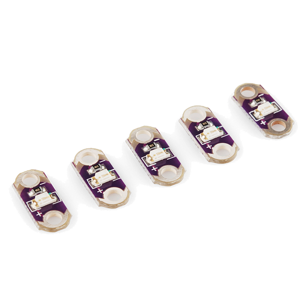 LilyPad LED - 5 pcs1 Packung
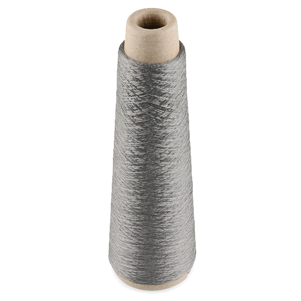 Conductive Thread - 60g (Stainless Steel)1 Spule
 Hand Sewing Needles (Assorted, 30-Pack)1 Packung
 Wool Felt Sheet1 Blatt
Connect the programmer
Connect the programmer
Plug the LilyPad FTDI onto the programming header and connect the USB cable to your computer. Open the Arduino IDE and select the LilyPad Arduino board and its serial port.
Materialien für diesen Schritt:
 LilyPad FTDI Basic Breakout - 5V1 Stück
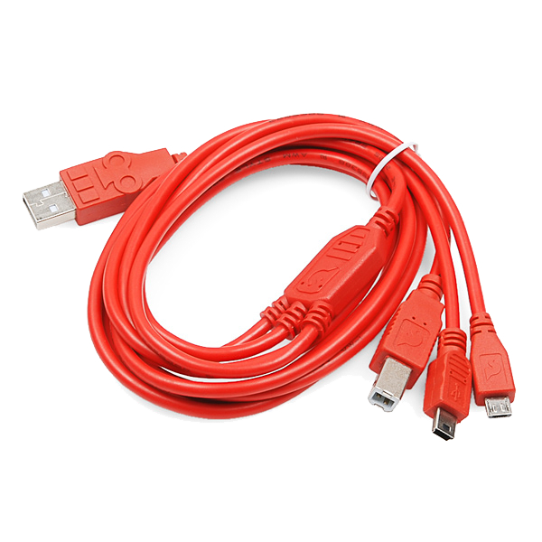 SparkFun Cerberus USB Cable - 1.8 meter1 Stück
Benötigte Werkzeuge:
 Computer with Arduino IDE
Upload the night-light sketch
Upload the night-light sketch
Paste this sketch and click Upload. It reads the light sensor and turns the LED on whenever the room is darker than the threshold.
Calibrate the threshold
Calibrate the threshold
Cover the sensor with your hand — the LED should come on; in a bright room it should stay off. If it triggers too early or too late, change the threshold number in the sketch and re-upload: higher turns it on in more light, lower waits for darker.
Go wireless and wear it
Go wireless and wear it
Unplug the FTDI, sew a LilyPad coin-cell holder to the board (+ to +, - to -), drop in a CR2032 and switch on. Sew the felt onto a bag, hat or cushion — it now glows on its own whenever the light drops.
Materialien für diesen Schritt:
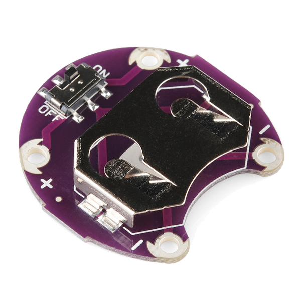 LilyPad Coin Cell Battery Holder - w/Switch - 20mm1 Stück
 CR2032 Coin Cell Battery1 Stück
Materialien
10- 1 Stück€17.00
- 1 Stück€7.00
- 1 Packung€4.00
- €34.00
- Platzhalter
- 1 BlattPlatzhalter
- €13.00
- €5.00
- 1 StückPlatzhalter
Benötigte Werkzeuge
1- Platzhalter
Verwandte Blueprints
Diese Blueprints teilen Wissen — Techniken, Materialien oder Prinzipien
Related blueprints
Other builds that share materials, tools, or techniques with this one.
CC0 Gemeinfrei
Dieser Blueprint ist unter CC0 veröffentlicht. Sie dürfen dieses Werk für jeden Zweck frei kopieren, ändern, verbreiten und verwenden, ohne um Erlaubnis zu fragen.
Unterstützen Sie den Maker, indem Sie Produkte über seinen Blueprint kaufen, wo er eine Maker-Provision von Anbietern festgelegt, verdient. Oder erstellen Sie eine neue Iteration dieses Blueprints und verbinden Sie ihn in Ihrem eigenen Blueprint, um Einnahmen zu teilen.