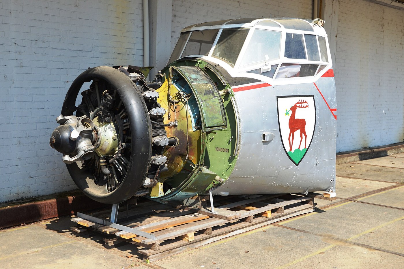


The NACA Cowling
Anweisungen
Build a finned cylinder rig and measure bare-engine drag
Build a finned cylinder rig and measure bare-engine drag
Establish the problem with numbers before shaping anything.
- Make a mock radial: a hub disc with five or seven finned cylinders arranged radially, from aluminium tube with slotted fins.
- Fit heater elements inside the cylinders so you can put a known, constant heat into them.
- Mount the assembly in the wind tunnel on the drag balance.
- At a fixed airspeed, record the drag and let the cylinder temperature settle. Record that too.
You now have the two numbers the whole design must trade between: drag, and steady-state cylinder temperature at a known heat input. Any change is only an improvement if it moves one without ruining the other.
Reverse-engineering note: the fins are the reason this works at all. A bare cylinder has very little surface; fins multiply it several times over, and their spacing matters — too close and the boundary layers from adjacent fins merge and choke the gap, too far apart and you have wasted metal. Measure your fin pitch and record it, because it is a variable you may want to change later.Materialien für diesen Schritt:
 Aluminiumrohr1 Stück
 Aluminiumplatte1 Stück
 Heizpatrone5 Stück
 Thermoelement mit Anzeige2 Stück
Benötigte Werkzeuge:
 Metalldrehmaschine
 Standbohrmaschine
 Feilensatz
 Digitaler Messschieber 6 Zoll
 Infrarot-Thermometer
 Federwaage
 Klare Schutzbrille
Cover it badly, and prove the naive fix fails
Cover it badly, and prove the naive fix fails
Do the obvious thing first, so the clever thing has something to beat.
- Make a plain cylindrical fairing that encloses the engine with a simple open front and closed sides.
- Repeat the measurement at the same airspeed and heat input.
- Record drag and temperature.
Drag falls usefully — and the cylinder temperature climbs, probably alarmingly. This is the trade everyone believed was fundamental, and you have just reproduced it. Air enters the front, finds no organised way out, stagnates inside the cowl and stops carrying heat away.
Watch the smoke around the exit region. You will see recirculation: air going round in circles inside the cowling rather than passing through. Air that has already been heated and cannot leave is not cooling air, it is insulation.Materialien für diesen Schritt:
 Aluminiumblech1 Blatt
 Stahlnieten30 Stück
Benötigte Werkzeuge:
FeilensatzStandbohrmaschineDigitaler Messschieber 6 ZollInfrarot-ThermometerFederwaage Räucherstäbchen zur RauchsichtbarmachungKlare Schutzbrille
 Nietsatz
 Niethammer
Shape the cowl as an aerofoil and open a controlled exit
Shape the cowl as an aerofoil and open a controlled exit
The NACA insight is that the cowl is not a cover. It is an annular wing.
- Reshape the cowl so its cross-section is an aerofoil wrapped into a ring: a rounded leading edge, a gently curving outer surface, and a smoothly converging inner surface.
- Set the inlet area smaller than you think — the goal is a modest, high-pressure flow, not a flood.
- Open a controlled annular exit at the rear, where the outer surface has accelerated the flow and pressure is therefore LOW.
- Repeat the drag and temperature measurement.
Both numbers improve: less drag than the bare engine and cooler cylinders than the plain cover. The mechanism is a pressure difference deliberately created between inlet and exit. Air is pushed in at the high-pressure stagnation region ahead and sucked out at the low-pressure region behind, so it is driven THROUGH the fins rather than allowed to wander.
The ring-aerofoil shape also does something unexpected: at the right angle it generates a forward-pointing thrust component of its own, offsetting part of the remaining drag. The NACA cowling on some aircraft effectively cost nothing at all.
The gains were extraordinary — a Curtiss AT-5A gained roughly 30 km/h in the 1928 tests with no extra power, which is the kind of result that reorganises an industry. Almost every radial-engined aircraft after 1930 wears one.Materialien für diesen Schritt:
Aluminiumblech2 BlätterStahlnieten40 StückBenötigte Werkzeuge:
FeilensatzStandbohrmaschineDigitaler Messschieber 6 Zoll WinkelmesserInfrarot-ThermometerFederwaageRäucherstäbchen zur RauchsichtbarmachungKlare Schutzbrille
 Schleifpapier
Fit cowl flaps and make the cooling adjustable
Fit cowl flaps and make the cooling adjustable
A cowl sized for the worst case is wrong for every other case.
- Cut the rear exit into hinged segments that can open and close, varying the exit area.
- Measure drag and temperature at full open, half open and closed, at a fixed airspeed.
- Now repeat at a much lower airspeed.
The exit area that keeps the engine cool on a slow climb is far larger than the one it needs in fast cruise, and leaving it open in cruise wastes drag continuously. Cowl flaps make the cooling flow a control the pilot manages: open for climb when the air is slow and the engine is working hardest, closed for cruise when the air is fast and the engine is loafing.
This is the same reasoning as the leading-edge slat. A device sized for a brief, demanding condition penalises every other minute of the flight, so it becomes adjustable — either automatically, like the slat, or by the pilot, like cowl flaps. Forgetting to close them was a classic way to arrive late.Materialien für diesen Schritt:
Aluminiumblech1 Blatt Scharnierleiste (Klavierband)1 Stück
 Maschinenschrauben12 Stück
Benötigte Werkzeuge:
FeilensatzStandbohrmaschineDigitaler Messschieber 6 ZollInfrarot-ThermometerFederwaage DrehmomentschlüsselKlare Schutzbrille
Add baffles, and find where the cooling actually goes
Add baffles, and find where the cooling actually goes
A cowl gets air into the engine bay. Baffles decide which parts of the engine it touches.
- Fit thermocouples to the front and rear cylinders, and to the top and bottom of one cylinder.
- Run the rig and compare temperatures around the engine.
- Now fit baffle plates that block the easy paths and force air down between the fins and around the rear of each cylinder.
- Re-measure.
Without baffles the temperature spread around the engine is large — some cylinders run far hotter than others, and the rear of each cylinder runs hotter than the front. Air, like current, takes the easiest path; left alone it rushes through the gaps between cylinders and barely touches the fins it was admitted to cool.
The hottest single spot is usually the rear cylinder head, and on a real engine that is where detonation starts, where valves burn and where an engine is destroyed. The cowl solves the drag problem; the baffles solve the distribution problem; they are not the same problem and one does not substitute for the other.
This is why a set of cracked or missing baffles is a genuine airworthiness item rather than cosmetic tidying, and why they are shaped so closely to each cylinder. Any gap is a short circuit that steals flow from the fins.Materialien für diesen Schritt:
Aluminiumblech1 BlattThermoelement mit Anzeige4 Stück Hochtemperatur-Silikondichtmasse1 tube
Benötigte Werkzeuge:
FeilensatzStandbohrmaschineDigitaler Messschieber 6 ZollInfrarot-Thermometer WärmebildkameraRäucherstäbchen zur RauchsichtbarmachungKlare Schutzbrille
Materialien
9- 1 StückPlatzhalter
- 1 StückPlatzhalter
- 5 StückPlatzhalter
- 6 StückPlatzhalter
- 5 BlätterPlatzhalter
- 70 StückPlatzhalter
- Platzhalter
- 12 StückPlatzhalter
- Platzhalter
Benötigte Werkzeuge
14- Platzhalter
- Platzhalter
- Platzhalter
- Platzhalter
- Platzhalter
- Platzhalter
- Platzhalter
- Platzhalter
- Platzhalter
- Platzhalter
- Platzhalter
- Platzhalter
- Platzhalter
- Platzhalter
Verwandte Blueprints
Diese Blueprints teilen Wissen — Techniken, Materialien oder Prinzipien

CC0 Gemeinfrei
Dieser Blueprint ist unter CC0 veröffentlicht. Sie dürfen dieses Werk für jeden Zweck frei kopieren, ändern, verbreiten und verwenden, ohne um Erlaubnis zu fragen.
Unterstützen Sie den Maker, indem Sie Produkte über seinen Blueprint kaufen, wo er eine Maker-Provision von Anbietern festgelegt, verdient. Oder erstellen Sie eine neue Iteration dieses Blueprints und verbinden Sie ihn in Ihrem eigenen Blueprint, um Einnahmen zu teilen.