Colaboración
ARTE
BELLEZA Y BIENESTAR
ARTESANÍA
CULTURA E HISTORIA
ENTRETENIMIENTO
MEDIO AMBIENTE
COMIDA Y BEBIDAS
INGENIERÍA INVERSA
CIENCIAS
DEPORTES
TECNOLOGÍA
TECNOLOGÍA VESTIBLE
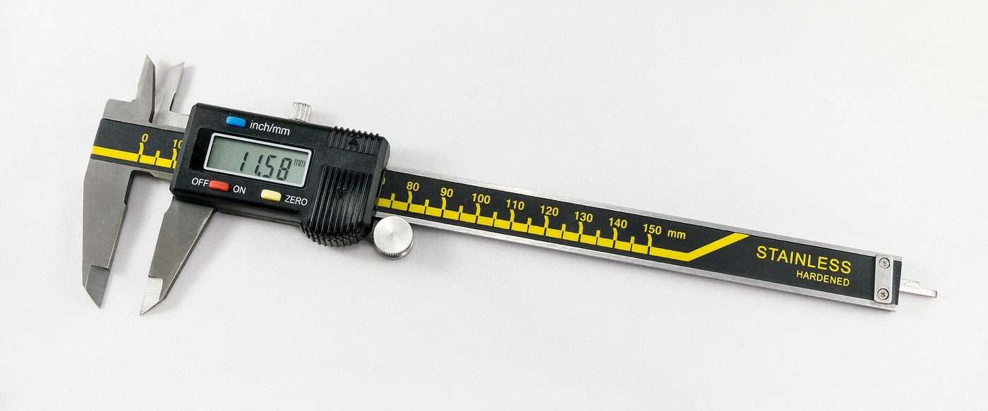


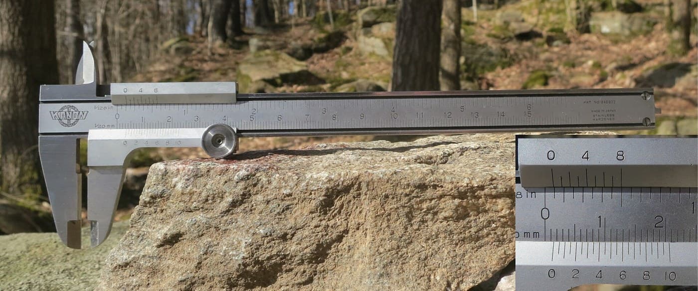
Digital Caliper: Capacitive Scale and Slider with Two-Chip Electronics (Baxter and Buehler, Starrett, 1986)
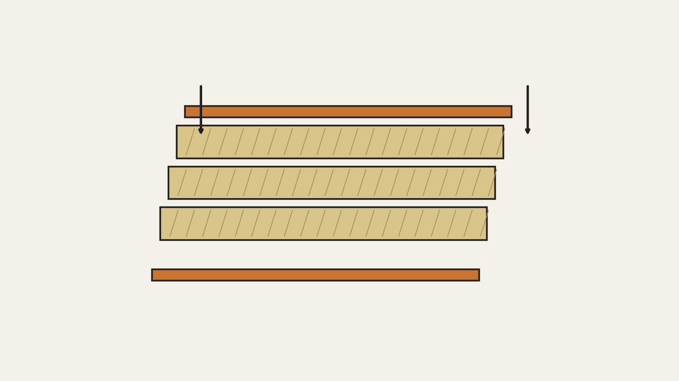
A six-inch caliper that reads out on a display. Under the slide, a strip of etched copper bars runs along the beam. Electrodes on the slider pass a signal through the bars by capacitance, and the slider's electronics count the bars crossed and work out the position in between.
Result: a digital caliper reading in inches or millimetres, repeatable to a ten-thousandth of an inch, with floating zero, peak hold and high/low limits. It runs on two 1.5 V cells at 10-50 microamps.
Source: L. K. Baxter and R. J. Buehler (L. S. Starrett Co.), US Patent 4,586,260 (1986). Unknown: the metal of the beam, slide and rod, their dimensions, the processor's program, and how the chips and display are made. Ours: the etchant, photoresist and glue. Picture: Wikimedia Commons.
Avanzado
2 days
Instrucciones
1
1
Etch the scale
Etch the scale
Etch the scale pattern onto a strip of copper-clad epoxy fibreglass with photoresist and etchant. Each copper bar is 0.40 inch long, with a wider centre 0.12 inch long and two ends 0.14 inch long. Space the bars on 0.05 inch centres: the centres sit 0.004 inch apart, the ends 0.025 inch apart. Run the pattern the full length of the scale. Ours: dry film resist and ferric chloride.
Materiales para este paso:
 Placa virgen para circuito impreso (cobreada)1 strip, length of the beam
Herramientas necesarias:
 Fotorresistente de película seca
 Disolución de cloruro férrico
 Guantes resistentes a productos químicos
2
2
Fix the scale into the beam
Fix the scale into the beam
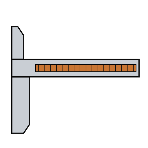
The beam is a metal bar with the fixed outside and inside jaws at one end, a wide shallow channel in its face and a second channel along its back. Fix the scale permanently into the face channel, copper up. The patent allows etching before or after this step. Not given: the metal, the dimensions and how the scale is fixed. Ours: epoxy.
Materiales para este paso:
 Regla del calibre1 with integral jaws
 Epoxi de dos componentes1 a little
Herramientas necesarias:
 Dimensiones desconocidas
3
3
Fit the parts to the circuit
Fit the parts to the circuit
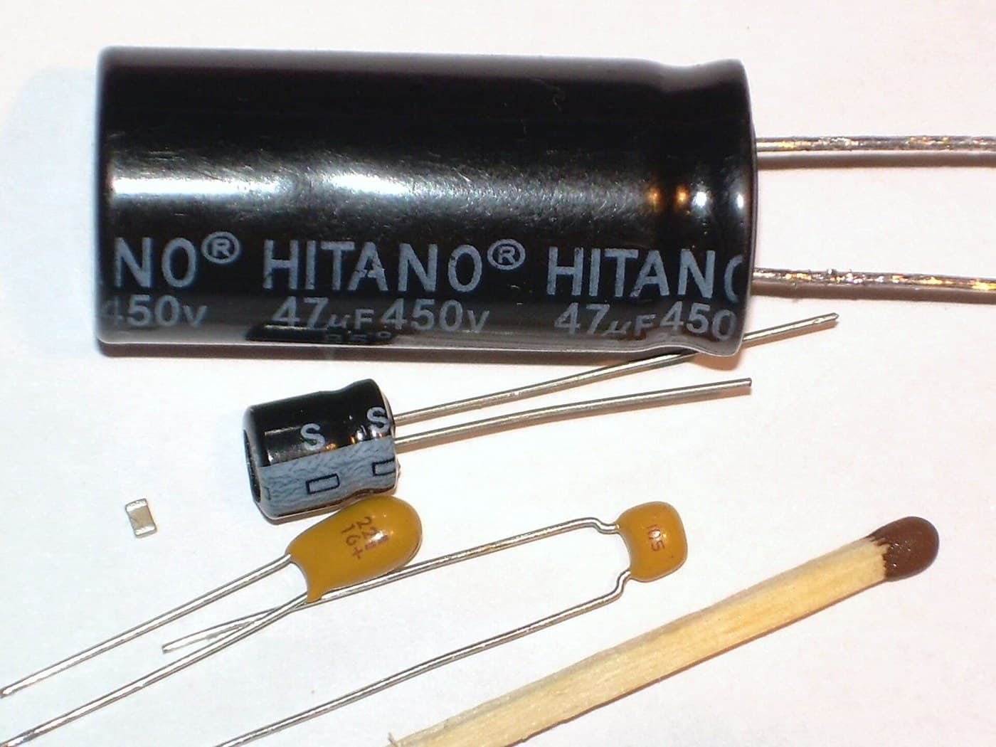
The circuit is one folded piece: a double-sided slider board joined by a flexible hinge to a circuit board. Its bottom face has two pickup electrodes, 0.750 x 0.110 inch and 0.0625 inch apart. On each side of them is an interdigitated transmitter array: fingers 0.115 inch long on 0.025 inch spacing, opening to 0.0375 inch at the centre. On the circuit board, solder or wire-bond the two chips: an NEC uPD7503 3 V processor (768 bits RAM, 2 kB ROM) and a CMOS gate array. Then fit the LCD, the 100 kHz crystal, the integrating capacitor and the MODE and SET buttons. Not given: the processor's program. Ours: a capacitor from a kit.
Materiales para este paso:
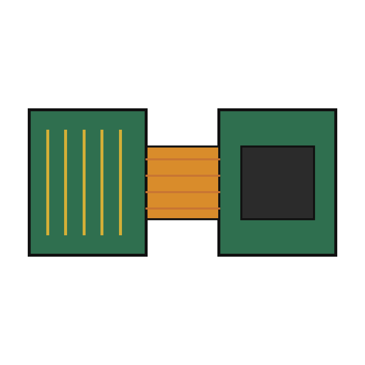 Circuito impreso rígido-flexible1 slider board + circuit board
 Circuito integrado2 uPD7503 CPU, CMOS gate array
 Pantalla LCD de segmentos1 5 digits
 Cristal de cuarzo1 100 kHz
 Kit de condensadores1 one integrating capacitor
 Pulsador2 MODE, SET
 Alambre de soldadura1 a little
Herramientas necesarias:
 Soldador de estaño
4
4
Build the slide
Build the slide
The slide frame wraps the back and edges of the beam and carries the movable jaws. Fix it to the depth rod, which runs in the back channel of the beam; the rod's free end is the depth gauge. Put the moulded plastic housing between the frame ends. Fasten two metal wear strips under the slider board, one on each side of the scale. They ride on the beam and connect the board's copper to it. Not given: the metal and sizes.
Materiales para este paso:
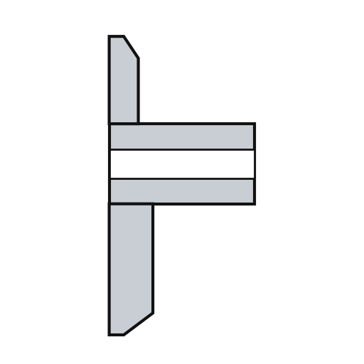 Marco de la corredera1 with jaws
 Metal desconocido1 depth rod and two wear strips
 Carcasa de la corredera1 pieza
Herramientas necesarias:
Dimensiones desconocidas Juego de destornilladores de precisión
5
5
Assemble and check
Assemble and check
Fold the circuit into the housing recess, slider board facing the scale, and screw it to the frame. The electrodes must lie parallel to the scale bars at every point of travel. Put the two 1.5 V cells (the patent says 'zinc oxide') in the battery pockets of the circuit. The display shows five digits, a ten-thousandths bar graph, a minus sign and 'mm', plus PEAK, LOW, HIGH and LIMIT. Ours: check the reading against a vernier caliper.
Materiales para este paso:
 Tornillos de máquina2 piezas
 Pila de botón de 1,5 V2 piezas
Herramientas necesarias:
Juego de destornilladores de precisión Calibre vernier
Materiales
15- 1 strip, length of the beamMarcador de posición
- 1 with integral jawsMarcador de posición
- 1 a littleMarcador de posición
- 1 slider board + circuit boardMarcador de posición
- 2 uPD7503 CPU, CMOS gate arrayMarcador de posición
- 1 5 digitsMarcador de posición
- 1 100 kHzMarcador de posición
- 1 one integrating capacitorMarcador de posición
- Marcador de posición
- 1 a littleMarcador de posición
- 1 with jawsMarcador de posición
- 1 depth rod and two wear stripsMarcador de posición
- 1 piezaMarcador de posición
- 2 piezasMarcador de posición
- 2 piezasMarcador de posición
Herramientas requeridas
7- Marcador de posición
- Marcador de posición
- Marcador de posición
- Marcador de posición
- 2 vendors sell this, none ship to you yetMarcador de posición
- Marcador de posición
- Marcador de posición
Materiales de Blueprints conectados

Este plano hace

Blueprints relacionados
Estos blueprints comparten conocimiento — técnicas, materiales o principios
CC0 Dominio público
Este Blueprint se publica bajo CC0. Eres libre de copiar, modificar, distribuir y usar este trabajo para cualquier propósito, sin pedir permiso.
Apoya al Maker comprando productos a través de su Blueprint, donde gana una Comisión del Maker establecida por los vendedores, o crea una nueva iteración de este Blueprint e inclúyela como conexión en tu propio Blueprint para compartir ingresos.