Colaboración
ARTE
BELLEZA Y BIENESTAR
ARTESANÍA
CULTURA E HISTORIA
ENTRETENIMIENTO
MEDIO AMBIENTE
COMIDA Y BEBIDAS
INGENIERÍA INVERSA
CIENCIAS
DEPORTES
TECNOLOGÍA
TECNOLOGÍA VESTIBLE
Friction Plunger Churn: Cream Pumped Through Openings You Close a Little More as It Thickens
Buttercup

Creado por

Buttercup

10. noviembre 2026IE
1
0
0
0
0

Friction Plunger Churn: Cream Pumped Through Openings You Close a Little More as It Thickens

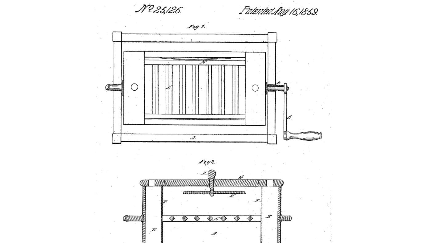
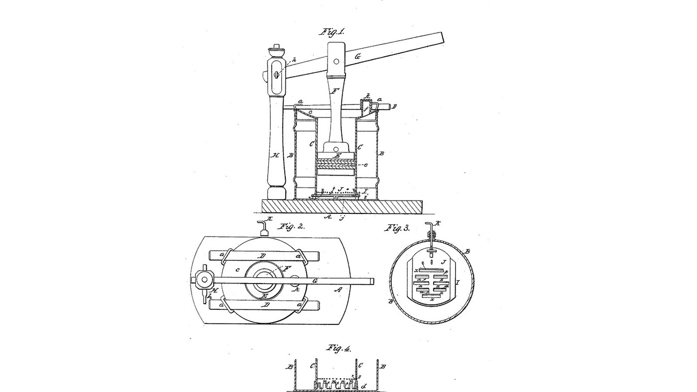
John J. Lehaye of Reading, Pennsylvania, received US 25,162, dated 16 August 1859, for a churn that works by friction. A hollow cylinder stands inside the cream vessel on two slotted plates. A packed plunger, worked by a long lever, draws the cream from the vessel into the cylinder through the slots and drives it back. A screw rod through a stuffing box in the vessel's side slides the upper plate, so the openings can be narrowed as the churning goes on. Lehaye gives no sizes; every size here is ours.
Intermedio
About 2 days, plus printing

Instrucciones

1

How hard the cream is rubbed through the openings

Cargando el cuaderno de Jupyter…
2

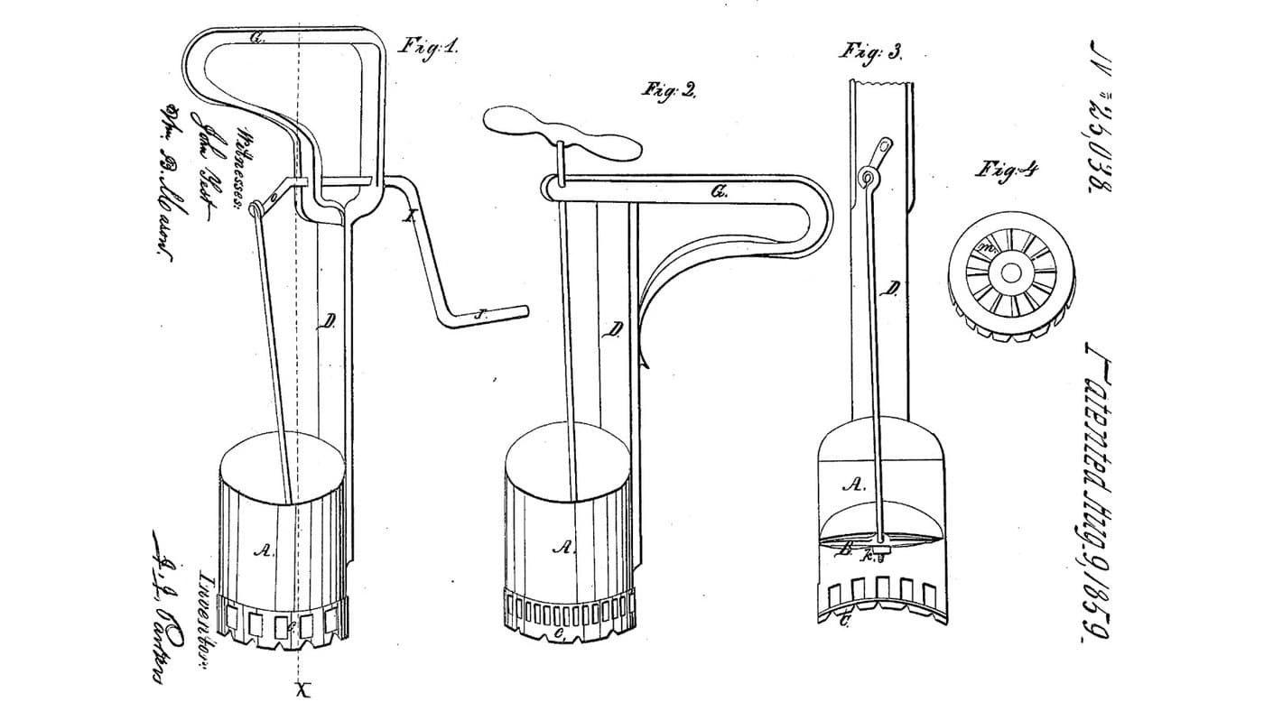
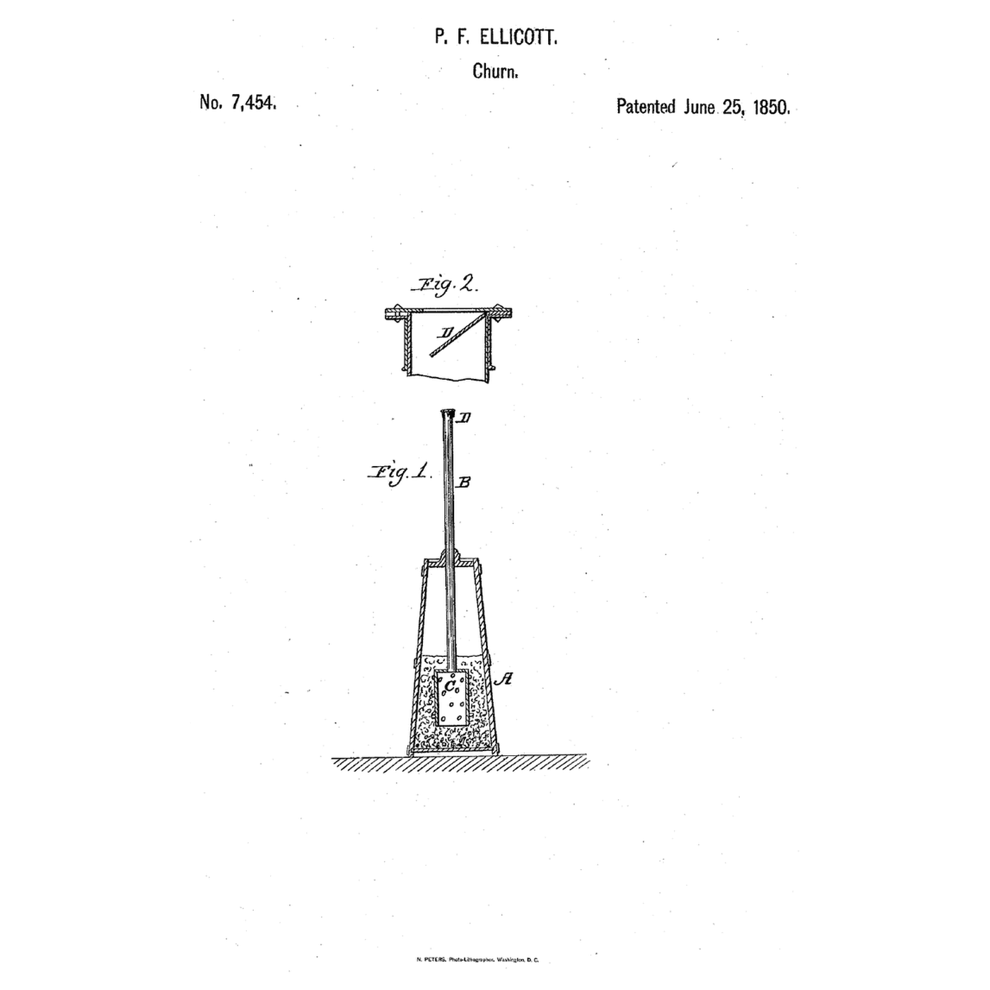
A piston that draws through a grate, the week before

Parker's beater pumped eggs through fixed openings. Lehaye's openings close a little more as the cream thickens.
3

Read US 25,162

"By causing the cream to pass and repass through contracted openings, and with considerable force, the friction of the cream against the edges of the openings has the effect of rapidly separating the butter from the whey at the same time the constant change in the course of the cream agitates the latter as effectually as the ordinary dashers."
4

Print the plate I

The 200 mm lower plate on four 20 mm legs i, with six 8 x 50 mm openings 18 mm apart and two guide flanges for plate J. Print it legs up. PETG, 0.2 mm layers, 30 % infill, 4 walls.
Archivo de DisenoSTLCC0 - Free
5

Print the plate J

The 116 x 64 mm sliding plate with six openings matching plate I's and a boss at one end for rod K's nut. PETG, 0.2 mm layers, 30 % infill, 4 walls.
Archivo de DisenoSTLCC0 - Free
6

Print the cylinder rings

One 86.5 mm ring of the cylinder C, 160 mm across with a 3 mm wall and a spigot on top. Print three. PETG, 0.2 mm layers, 30 % infill, 4 walls.
Archivo de DisenoSTLCC0 - Free
7

Print the bottom cylinder ring

The bottom ring, with an 18 mm notch in its lower edge for rod K. PETG, 0.2 mm layers, 30 % infill, 4 walls.
Archivo de DisenoSTLCC0 - Free
8

Print the plunger's upper plate

A 152 mm plate with a hub bored 6.4 mm across for rod F's pin. PETG, 0.2 mm layers, 30 % infill, 4 walls.
Archivo de DisenoSTLCC0 - Free
9

Print the plunger's lower plate

The plain 152 mm plate with a 6.4 mm hole in the middle. PETG, 0.2 mm layers, 30 % infill, 4 walls.
Archivo de DisenoSTLCC0 - Free
10

Print the stuffing box's inner half

The flanged boss that sits inside the bucket, with an O-ring groove in its face and two 4.4 mm screw holes. PETG, 0.2 mm layers, 30 % infill, 4 walls.
Archivo de DisenoSTLCC0 - Free
11

Print the stuffing box's outer half

The flanged boss outside the bucket, with a groove in its bore for a 6 mm O-ring round rod K. PETG, 0.2 mm layers, 30 % infill, 4 walls.
Archivo de DisenoSTLCC0 - Free
12

Print the vent tube

The 20 mm tube through the flange that lets the gases out. PETG, 0.2 mm layers, 30 % infill, 4 walls.
Archivo de DisenoSTLCC0 - Free
13

Print the vent's cover k

The push-on cover for the vent tube. PETG, 0.2 mm layers, 30 % infill, 4 walls.
Archivo de DisenoSTLCC0 - Free
14

Base A and column H

Cut an 18 mm plywood base 750 x 400 mm. Stand a hardwood column 70 x 70 mm, 643 mm tall, on it 290 mm from where the bucket's middle will be, glued and screwed from under the base. Saw a slot 24 mm wide and 100 mm deep in its top and bore it 12.4 mm across 40 mm below the top for the pin h.

Materiales para este paso:

Tablero contrachapadoTablero contrachapado1 pieza
Tabla de madera duraTabla de madera dura1 pieza
Cola de carpinteroCola de carpintero1 pieza
Tornillos para maderaTornillos para madera6 piezas

Herramientas necesarias:

Sierra de calarSierra de calar
SerruchoSerrucho
FormonesFormones
Taladro inalámbricoTaladro inalámbrico
Juego de brocas de palaJuego de brocas de pala
Juego de brocasJuego de brocas
Escuadra fijaEscuadra fija
Cinta métricaCinta métrica
15

Bucket B and the stuffing box

Screw the bucket's floor to the base. Drill a 20.4 mm hole in its side 30 mm above the floor, facing away from the column, and two 4.4 mm holes 19 mm either side of it. Lay a 30 x 2 mm O-ring in the inner half's groove, fit the halves inside and outside the wall and draw them together with two stainless M4 screws and lock nuts. Fill the bucket with water to check the box does not leak, then empty it.

Materiales para este paso:

Cubo de 20 litrosCubo de 20 litros1 pieza
Tornillos para maderaTornillos para madera4 piezas
Junta tóricaJunta tórica2 piezas
Tornillos de máquinaTornillos de máquina2 piezas
Tuerca autoblocante con inserto de nailonTuerca autoblocante con inserto de nailon2 piezas

Filamento PETGFilamento PETG1 pieza

Herramientas necesarias:

Impresora 3D de filamento (FDM)Impresora 3D de filamento (FDM)
Taladro inalámbricoTaladro inalámbrico
Juego de brocas de palaJuego de brocas de pala
Juego de brocasJuego de brocas
Juego de destornilladoresJuego de destornilladores
Llave inglesa ajustableLlave inglesa ajustable
AguaAgua
16

Plates I and J, and rod K

Press an M6 nut into plate J's boss. Lay J on plate I between its flanges and stand I on its legs in the middle of the bucket's floor. Cut 170 mm of M6 stainless threaded rod, bend 40 mm of one end to an L for a handle, push the straight end in through the stuffing box with a 6 mm O-ring in its bore and screw it into J's nut. Turn K both ways: J slides until its openings line up with I's, and closes them after 8 mm.

Materiales para este paso:

Tuerca hexagonalTuerca hexagonal1 pieza
Varilla roscadaVarilla roscada1 pieza
Junta tóricaJunta tórica1 pieza

Herramientas necesarias:

Sierra para metalesSierra para metales
Tornillo de bancoTornillo de banco
Llave inglesa ajustableLlave inglesa ajustable
17

Cylinder C, flange c, staples and wedges

Stack the four rings on plate I, the notched one at the bottom over rod K. Cut the flange from 12 mm plywood, a ring 304 mm across with a 154 mm hole, and bore a 16 mm hole 125 mm from its middle for the vent. Set it on the bucket's rim over the cylinder's top. Fit four stainless U-bolts through the bucket wall just under the rim, two each side, and drive two tapered hardwood wedges, 340 x 30 mm and 16 mm at their thick end, through them over the flange so it presses the cylinder down on the plates. Push the vent tube into its hole and its cover on top.

Materiales para este paso:

Tablero contrachapadoTablero contrachapado1 pieza
Abrazadera en UAbrazadera en U4 piezas
Tabla de madera duraTabla de madera dura1 pieza
Filamento PETGFilamento PETG1 pieza

Herramientas necesarias:

Sierra de calarSierra de calar
Juego de brocas de palaJuego de brocas de pala
Taladro inalámbricoTaladro inalámbrico
Juego de brocasJuego de brocas
SerruchoSerrucho
Llave inglesa ajustableLlave inglesa ajustable
18

Plunger E, rod F and arm G

Cut two 153.9 mm discs of 3 mm food-grade silicone sheet and bolt them between the plunger plates through the middle, hub up; the silicone's edge is the packing e and should slide in the cylinder with a light drag. Saw a slot in each end of a 22 mm hardwood dowel 470 mm long between pin centres and pin its lower end to the plunger's hub with a 6 mm stainless bolt. Make the arm G from hardwood 40 x 22 mm, 930 mm long, bore it 12.4 mm 30 mm from one end for the pin h and 6.4 mm 290 mm from that for rod F, then bolt it into the column's slot with a 12 mm bolt and pin rod F to it.

Materiales para este paso:

Lámina de caucho de siliconaLámina de caucho de silicona1 pieza
Surtido de tornillos hexagonalesSurtido de tornillos hexagonales4 piezas
Tuerca autoblocante con inserto de nailonTuerca autoblocante con inserto de nailon4 piezas

Arandela planaArandela plana4 piezas
Espigas de madera duraEspigas de madera dura1 pieza
Tabla de madera duraTabla de madera dura1 pieza

Herramientas necesarias:

TijerasTijeras
SerruchoSerrucho
Taladro inalámbricoTaladro inalámbrico
Juego de brocasJuego de brocas
Llave inglesa ajustableLlave inglesa ajustable
Cinta métricaCinta métrica
19

The build in 3D

FreeCAD model of this build, cut open: the bucket on its base, the slotted plates I and J with rod K through the stuffing box, the cylinder of four rings under the flange, the wedges and staples, the vent, and the plunger on rod F worked by the arm G from the column H. Checked over the lever's whole travel and with plate J slid fully.
Archivo de DisenoBLENDCC0 - Free
20

Churn

With plate J slid so all the openings are open, pour about 10 litres of heavy cream at about 15 °C into the bucket, checked with the thermometer. Work the arm about once a second, timing it. As the cream thickens, give rod K a turn now and then to close the openings a little. Lift the vent's cover now and then to let the gas out. When the butter comes, knock the wedges out, lift out the flange, the cylinder and the plunger, pour off the buttermilk, wash the butter in cold water until it runs clear, work in a pinch of salt and weigh it.

Materiales para este paso:

Crema de leche espesaCrema de leche espesa10 l
Sal marina gruesaSal marina gruesa1 pieza
AguaAgua1 pieza

Herramientas necesarias:

Termómetro de sonda permanenteTermómetro de sonda permanente
CronómetroCronómetro
Báscula digital de cocinaBáscula digital de cocina
Bol grande de acero inoxidableBol grande de acero inoxidable
21

Troubleshooting

Friction plunger churn troubleshooting.

Flow

Loading...
22

History and honest limits

**John J. Lehaye** of Reading, Pennsylvania, assignor to himself and John Tucker of Philadelphia, US 25,162, 16 August 1859, "Churn". He claimed the vessel B, cylinder C and plunger E in combination with means for enlarging or contracting the openings between the cylinder and the vessel. He gives no sizes, so every size here is ours; the U-bolts are his staples a, the O-ring box his stuffing box, and silicone his packing. His Fig. 4 alternative, projections on the cylinder's foot and on a ring in the vessel's bottom, turned to open or close the gaps, is not built. He also offered the machine as an egg beater and for mixing curds.

Materiales

19

Herramientas requeridas

19

Archivos de diseño

11

CC0 Dominio público

Este Blueprint se publica bajo CC0. Eres libre de copiar, modificar, distribuir y usar este trabajo para cualquier propósito, sin pedir permiso.

Apoya al Maker comprando productos a través de su Blueprint, donde gana una Comisión del Maker establecida por los vendedores, o crea una nueva iteración de este Blueprint e inclúyela como conexión en tu propio Blueprint para compartir ingresos.

Discusión

(0)

Iniciar sesión para unirte a la discusión

Cargando comentarios...