Colaboración
ARTE
BELLEZA Y BIENESTAR
ARTESANÍA
CULTURA E HISTORIA
ENTRETENIMIENTO
MEDIO AMBIENTE
COMIDA Y BEBIDAS
INGENIERÍA INVERSA
CIENCIAS
DEPORTES
TECNOLOGÍA
TECNOLOGÍA VESTIBLE
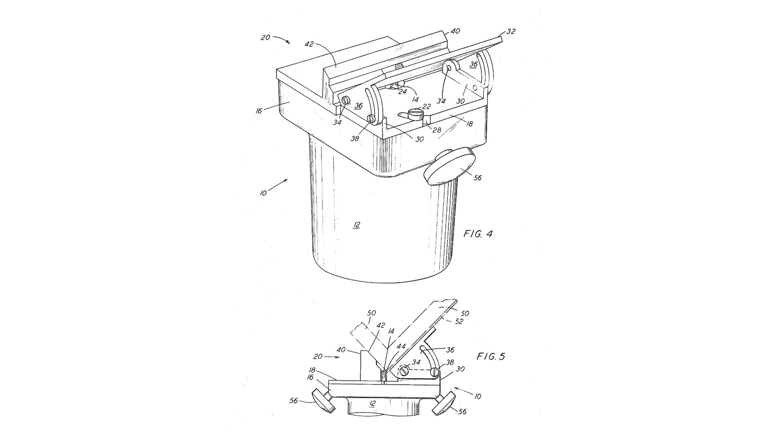


Laminate Bevel Trimmer: Two Pads at Right Angles Hold a Small Router at 45 Degrees on a Corner (Roche, 1971)
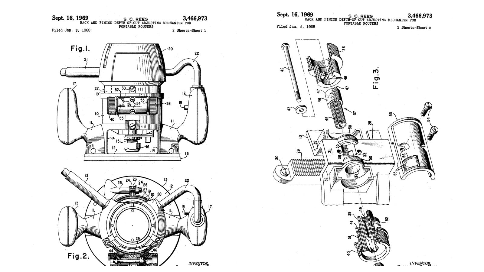
Edward Noland Roche of Cockeysville, Maryland, received US 3,628,579, dated 21 December 1971, for a small router that bevels plastic laminate in place. Laminate is usually trimmed after it is glued down, and a mitred corner meant mitring the wood underneath too. Roche's tool rides on the corner of the already-built carcass. A fixed pad with a 45 degree face sits on the top surface, a tilting pad sits on the side face, and the cutter between them bevels the laminate's edge inwards, exactly to the edge beneath it. The guide base swings slightly on a pivot to line the pad up with the cutter.
We print the motor unit, base and pads in PETG round a small DC motor. The 45 degrees is his; the other sizes are ours.
Avanzado
About 2 days
Instrucciones
1
1
Why the substrate needs no mitre
Why the substrate needs no mitre
Cargando el cuaderno de Jupyter…
2
2
Read US 3,628,579
Read US 3,628,579
"This pad 40 has a raised guide face 42 that slopes at a 45 degree plane which extended, coincides with the far edge of the cutting tool." "An inwardly sloping bevel 58 which exactly conforms with the edge of the substrate 50 results."
3
3
Print the motor unit
Print the motor unit
The motor unit 12: a tube for a 42 mm motor with the square faceplate 16 at its end, an 18 mm hole and two M4 holes for the motor, a hole to tap M4 for the pivot stud 26 and one to tap M5 for the adjusting screw 22, and two handle bosses. Print it faceplate down. PETG, 0.2 mm layers, 40 % infill, 5 walls.
4
4
Print the guide base
Print the guide base
The base 18: a flat plate with the clearance hole 24, the stud hole, the curved slot 28, the fixed pad 40 with its 45 degree face 42, and the two ears 30. Print it plate down. PETG, 0.2 mm layers, 40 % infill, 5 walls.
5
5
Print the adjustable pad
Print the adjustable pad
The pad 32 with its two cheeks 36, each with a hole for the pivot screw 34 and an arc slot for the locking screw 38. Print it plate down. PETG, 0.2 mm layers, 40 % infill, 5 walls.
6
6
Motor unit
Motor unit
Tap the faceplate's two holes M4 and M5. Fit the collet adapter on the motor, stand the motor in the tube with its face on the faceplate and the collet through the hole, screw it in with two M4 screws, and wire it through a toggle switch to the DC supply. Turn two hardwood knobs 56 and bolt them to the handle bosses.
Materiales para este paso:
 Filamento PETG1 pieza
 Motor eléctrico1 pieza
 Motor Shaft Collet Adapter1 pieza
 Tornillo de cabeza cilíndrica con hexágono interior2 piezas
 Interruptor de palanca1 pieza
 Cable de conexión1 pieza
 Tubo termorretráctil1 pieza
 Tabla de madera dura1 pieza
 Surtido de tornillos hexagonales2 piezas
 Tuerca hexagonal2 piezas
Herramientas necesarias:
 Impresora 3D de filamento (FDM)
 Juego de machos y terrajas
 Volvedor de machos
 Fuente de alimentación de corriente continua
 Soldador eléctrico
 Juego de llaves Allen
 Torno de madera
 Taladro inalámbrico
 Juego de brocas
7
7
Guide base, pads and setting
Guide base, pads and setting
Fit a 1/4 inch straight bit in the collet. Lay the base on the faceplate, the cutter through its hole; screw an M4 screw through the corner hole into the faceplate as the pivot stud 26, and an M5 screw with a washer through the curved slot as the adjusting screw 22. Hold a straightedge on the fixed pad's sloping face, reaching past the cutter, and swing the base on its stud until the straightedge just touches the cutter's far edge; tighten the adjusting screw. Hang the adjustable pad on the ears with two M4 pivot screws 34 and two M4 locking screws 38 through its arc slots; set it square to the fixed pad's face for 90 degree corners and lock it.
Materiales para este paso:
Tornillo de cabeza cilíndrica con hexágono interior6 piezas Arandela plana3 piezas
Herramientas necesarias:
 Juego de fresas para fresadoraJuego de llaves Allen
 Escuadra combinada
 Transportador de ángulos
8
8
Bevel a laminate edge
Bevel a laminate edge
Clamp a sheet temporarily to one face of the built carcass with its edge standing proud past the corner. Hold the tool by its knobs at 45 degrees, fixed pad on the top surface and adjustable pad on the side, switch on and run it along the edge until both pads bear on the work and the cutting stops: the laminate's edge is bevelled exactly to the corner. Take the sheet off, keep it for gluing, and do the next face.
Herramientas necesarias:
 Sargento
 Gafas de seguridad
9
9
Troubleshooting
Troubleshooting
Laminate trimmer troubleshooting.
Flow
Loading...
10
10
History and honest limits
History and honest limits
**Edward Noland Roche** of Cockeysville, Maryland, US 3,628,579, dated 21 December 1971, filed 18 November 1969. He claimed a laminate chamfering machine with a faceplate and cylindrical cutter, a guide base pivoted at one corner and locked through "a curved slot formed therein to the radius from said pivot means", pads on the base's two halves, and "a guide pad having a raised guide face sloping at a predetermined plane which extended coincides with the far edge of said cutting tool". He gives the 45 degree slope and no sizes; ours are printed PETG parts round a small DC motor, and we set the pad to the cutter with a straightedge rather than by a figure.
Materiales
11- 1 piezaMarcador de posición
- 1 piezaMarcador de posición
- 1 piezaMarcador de posición
- Marcador de posición
- Marcador de posición
- Marcador de posición
- 1 piezaMarcador de posición
- 1 piezaMarcador de posición
- 2 piezasMarcador de posición
- 2 piezasMarcador de posición
- 3 piezasMarcador de posición
Herramientas requeridas
14- Marcador de posición
- Marcador de posición
- Marcador de posición
- Marcador de posición
- Marcador de posición
- Marcador de posición
- Marcador de posición
- 1 vendor sell this, none ship to you yetMarcador de posición
- Marcador de posición
- 1 vendor sell this, none ship to you yetMarcador de posición
- Marcador de posición
- Marcador de posición
- Marcador de posición
- Marcador de posición
Archivos de diseño
3Este plano hace

Blueprints relacionados
Estos blueprints comparten conocimiento — técnicas, materiales o principios
CC0 Dominio público
Este Blueprint se publica bajo CC0. Eres libre de copiar, modificar, distribuir y usar este trabajo para cualquier propósito, sin pedir permiso.
Apoya al Maker comprando productos a través de su Blueprint, donde gana una Comisión del Maker establecida por los vendedores, o crea una nueva iteración de este Blueprint e inclúyela como conexión en tu propio Blueprint para compartir ingresos.