Colaboración
ARTE
BELLEZA Y BIENESTAR
ARTESANÍA
CULTURA E HISTORIA
ENTRETENIMIENTO
MEDIO AMBIENTE
COMIDA Y BEBIDAS
INGENIERÍA INVERSA
CIENCIAS
DEPORTES
TECNOLOGÍA
TECNOLOGÍA VESTIBLE
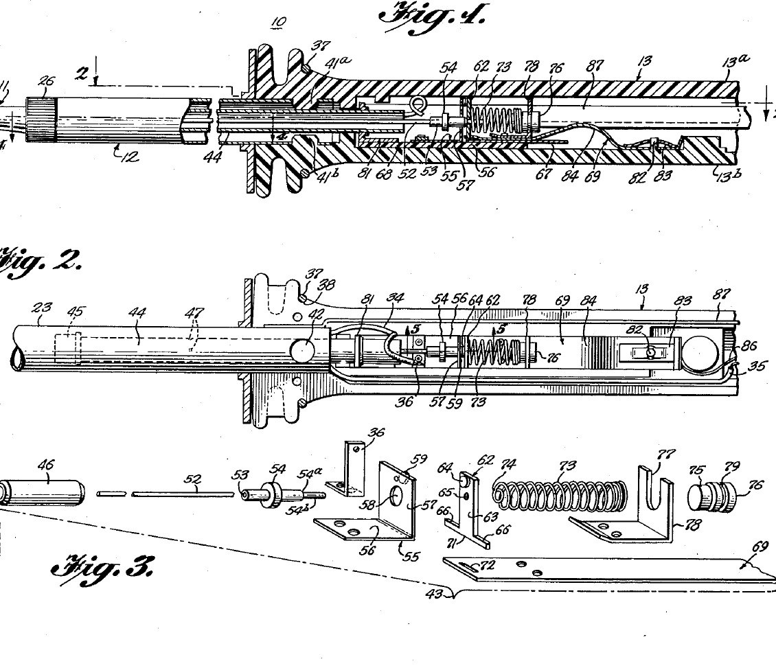


Soldering Iron: Temperature Controlled by a Curie-Point Tip and a Magnet Switch (Weller, US 3,188,448, 1965)
A soldering iron that holds its own tip temperature. At the back of the copper tip sits a slug of nickel-iron alloy that stops being magnetic above a set temperature (its Curie point). A small Alnico magnet behind it is pulled forward while the slug is cool, closing a switch that feeds the heater; once the tip is hot the slug lets go, a steel bushing pulls the magnet back and the switch opens. Swap tips to choose 600, 700 or 800 °F.
Result: a 55-watt temperature-controlled iron idling near 700 °F instead of running ever hotter.
Source: C. E. Weller, US 3,188,448 (1965). Unknown: the plating baths, the heater wire and insulation, most sizes. Picture: the patent drawing.
Avanzado
Unknown
Instrucciones
1
1
Make the tip and control slug
Make the tip and control slug
Turn the tip from tellurium copper: a cylindrical body, a taper and a chisel end (any shape suits the work). Plate it first with iron, which keeps the copper out of the molten solder, then with nickel, which shuts out the air. Bore its rear end and fit tightly into it the shank of a slug of thermomagnetic nickel-iron alloy, such as 48 % nickel, 3 % molybdenum and the rest iron, or about 43 % nickel and the rest iron. The alloy sets the control point: make tips for 600, 700 and 800 °F. Not given: the plating baths, sizes.
Materiales para este paso:
 Barra de cobre al telurio1 tip
 Aleación termomagnética de níquel-hierro1 control slug
Herramientas necesarias:
 Torno de metal
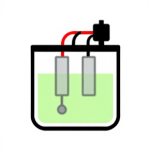 Kit de galvanoplastia
 Dimensiones desconocidas
2
2
Wind the heater barrel
Wind the heater barrel
Make the barrel of two stainless steel tubes: an inner spool the tip slides into snugly, and an outer cover tube joined to it at the front, with a thread and screw cap to hold the tip. In the space between them wind the heater from one length of resistance wire: an inner layer, then an outer layer wound the opposite way so their fields cancel, with insulating sheet inside, between and outside the layers. Silver-solder heat-resistant leads to its ends. Ours: nichrome wire. Not given: the insulating sheet, the turns.
Materiales para este paso:
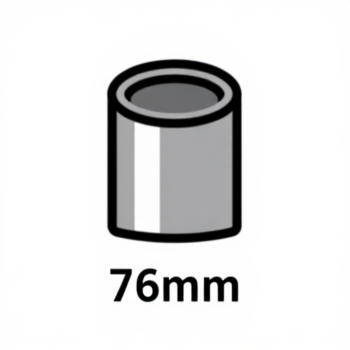 Tubo de acero inoxidable2 spool and cover tube
 Hilo de nicrom1 heater
 Material aislante desconocido1 three sheet layers
 Metal desconocido1 leads
 Soldadura de plata1 as needed
Herramientas necesarias:
 Soplete de propanoTorno de metal
3
3
Build the magnet switch
Build the magnet switch
In a stainless steel sleeve about 2.4 in long, close the front with a non-magnetic thermal bushing. Behind it slides a cylindrical Alnico V magnet, then a non-magnetic spacer about 0.032 in thick, then a cold-drawn steel bushing about 0.50 in long held by dents in the sleeve; the magnet's stroke is about 0.015 in. A push rod runs from the magnet through the bushing to an insulator. On a melamine plate, hinge a moving contact between a thin conducting strip and a holding strip, facing a flexible contact; a spring of fourteen coils of 0.010 in music wire, 0.210 in across, presses the moving contact toward the flexible one. Rivet the spring bracket to the holding strip. Not given: the contact metals.
Materiales para este paso:
Tubo de acero inoxidable1 sleeve Imán de Alnico1 pieza
 Redondo de acero dulce1 magnetic bushing, push rodMetal desconocido1 thermal bushing, spacer, contacts, strips, brackets
 Material desconocido1 insulator
 Placa de melamina1 base plate
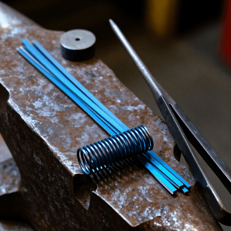
 Alambre de acero para muelles1 0.010 in music wire spring
Herramientas necesarias:
Torno de metal Juego de remachar
 Alicates de punta redonda
4
4
Assemble the handle and use
Assemble the handle and use
Mould the handle in two plastic halves with a socket at the front whose bosses lock the cover tube. Lay in the switch unit, held only by the bowed tail of its holding strip on an anchor pin with a speed nut, so it floats and its thermal bushing presses on the tip's slug. Wire the heater, the switch and a ground lead from the cover tube to the cord. Rivet the halves near the butt and fit a split ring near the front. In use, below the control point the slug pulls the magnet forward and the spring closes the contacts; above it the steel bushing pulls the magnet back and the push rod opens them. At idle the heater runs only about 30 to 40 % of the time. Not given: the plastic.
Materiales para este paso:
Material desconocido1 handle halvesMetal desconocido1 rivet, split ring, speed nut Cable flexible con clavija1 pieza
Herramientas necesarias:
 Máquina de moldeo por inyecciónJuego de remachar
Materiales
13- Marcador de posición
- 1 control slugMarcador de posición
- 1 sleeveMarcador de posición
- 1 heaterMarcador de posición
- 1 three sheet layersMarcador de posición
- 1 rivet, split ring, speed nutMarcador de posición
- 1 as neededMarcador de posición
- 1 piezaMarcador de posición
- 1 magnetic bushing, push rodMarcador de posición
- 1 handle halvesMarcador de posición
- 1 base plateMarcador de posición
- 1 0.010 in music wire springMarcador de posición
- 1 piezaMarcador de posición
Herramientas requeridas
7- Marcador de posición
- Marcador de posición
- Marcador de posición
- Marcador de posición
- Marcador de posición
- Marcador de posición
- Marcador de posición
Materiales de Blueprints conectados

Este plano hace

CC0 Dominio público
Este Blueprint se publica bajo CC0. Eres libre de copiar, modificar, distribuir y usar este trabajo para cualquier propósito, sin pedir permiso.
Apoya al Maker comprando productos a través de su Blueprint, donde gana una Comisión del Maker establecida por los vendedores, o crea una nueva iteración de este Blueprint e inclúyela como conexión en tu propio Blueprint para compartir ingresos.