Collaboration
ART
BEAUTÉ ET BIEN-ÊTRE
ARTISANAT
CULTURE ET HISTOIRE
DIVERTISSEMENT
ENVIRONNEMENT
NOURRITURE ET BOISSONS
INGÉNIERIE INVERSE
SCIENCES
SPORTS
TECHNOLOGIE
TECHNOLOGIE PORTABLE
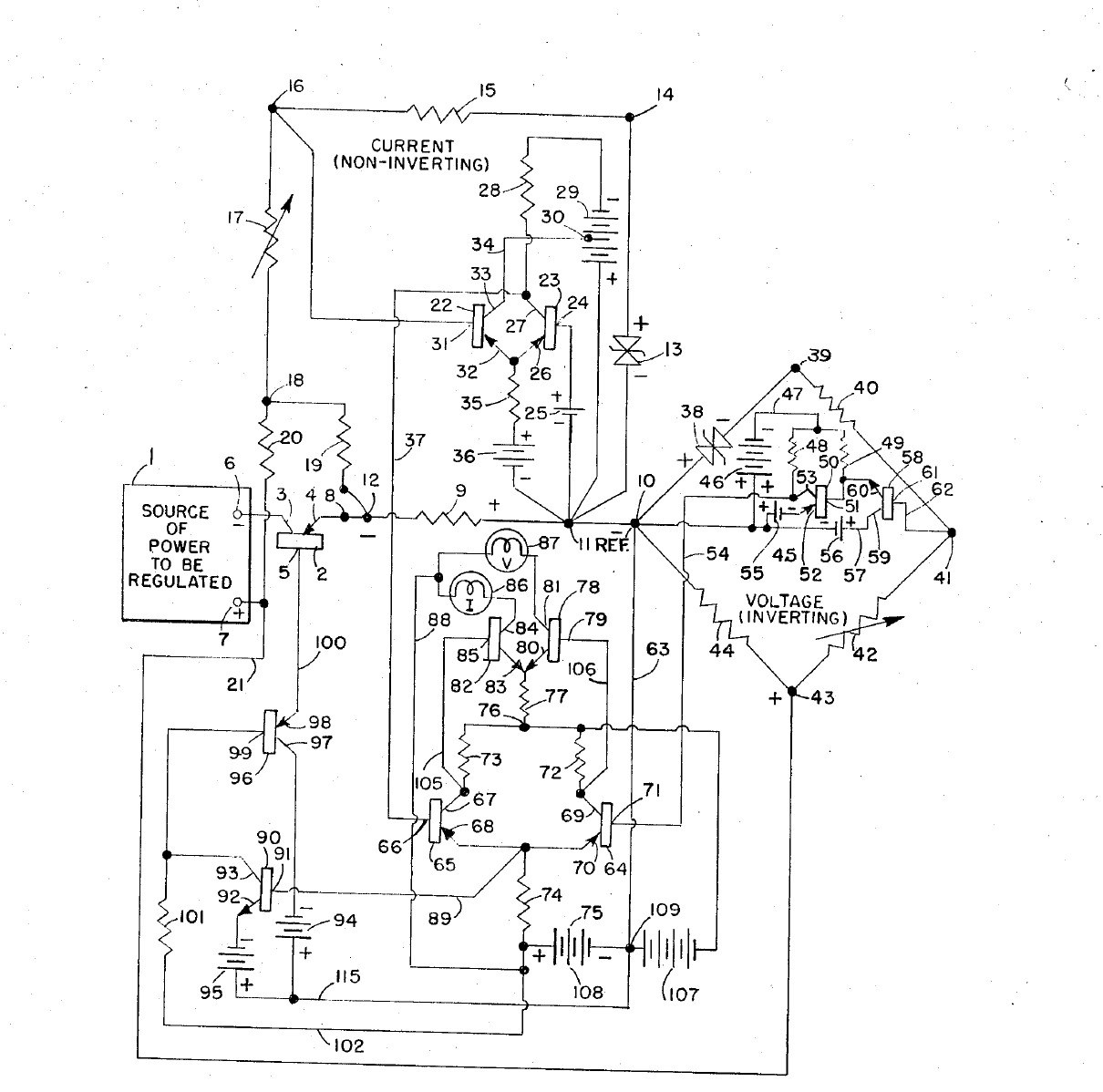


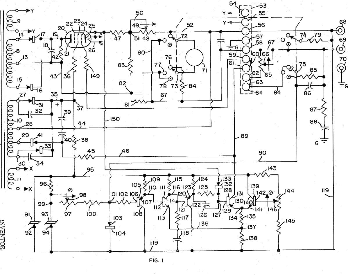
Adjustable Bench Power Supply: Constant Voltage / Constant Current with Cross-Over Lamps (Gately, Forbro, US 3,303,411, 1967)
An all-transistor bench supply with two knobs: one sets the voltage, the other the current. It holds the set voltage until the load tries to draw more than the set current, then switches at once to holding the current, and back again, with no in-between state. Two lamps show which mode is in control.
Result: an adjustable constant-voltage / constant-current DC supply with mode lamps.
Source: J. R. Gately (Forbro Design), US 3,303,411 (1967). Unknown: all component values and ratings. Builds on the same inventor's 1966 current-limited supply. Picture: the patent drawing.
Avancé
Unknown
Consignes
1
1
Build the raw supplies
Build the raw supplies
In a case, wire the cord through a switch and fuse to two power transformers, each with rectifiers and a filter: one gives the main power to be regulated, the other the bias supplies, held steady by Zener diodes. Not given: the voltages. Ours: the case, switch and fuse.
Matériaux pour cette étape :
 Boîtier en aluminium1 pièce
 Cordon souple avec fiche1 pièce
 Interrupteur à levier1 pièce
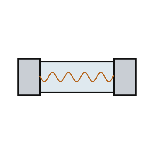 Fusible1 pièce
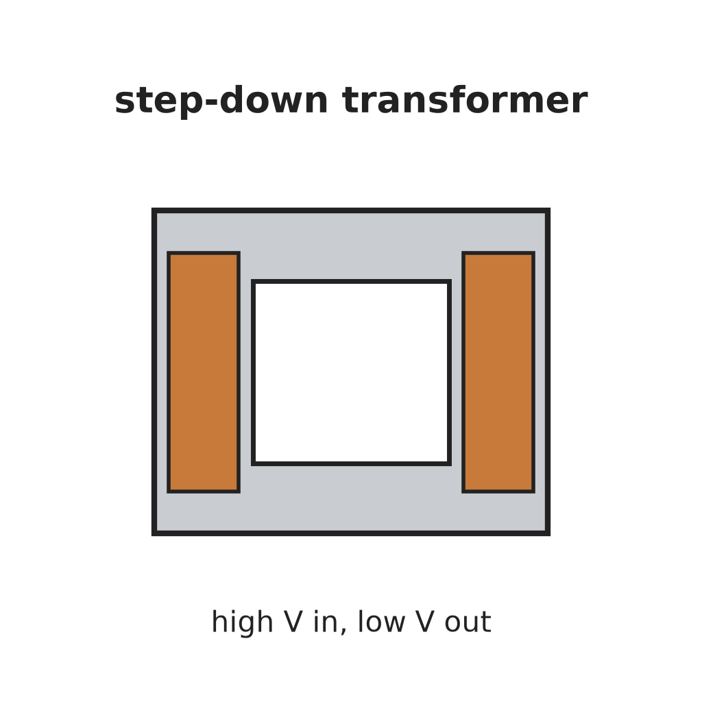 Transformateur abaisseur2 pièces
 Diode6 rectifiers
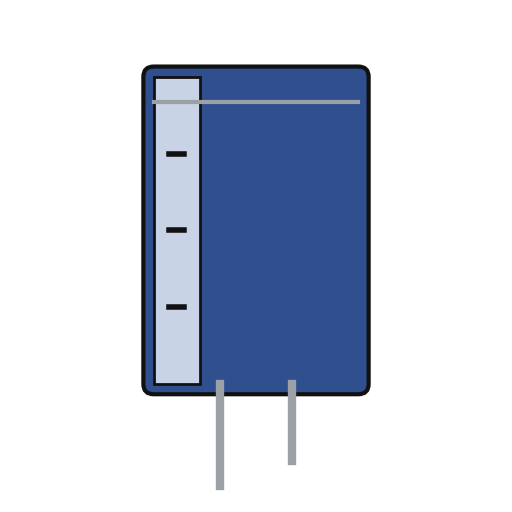 Condensateur électrolytique3 filters
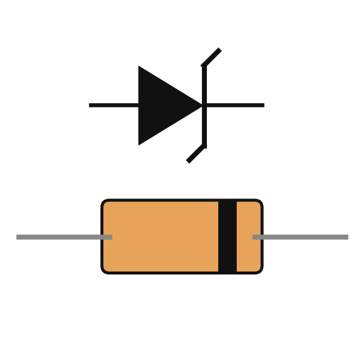 Diode Zener2 bias
Outils nécessaires :
 Chignole à main
 Jeu de tournevis
2
2
Fit the pass transistor and current bridge
Fit the pass transistor and current bridge
Put a power transistor on a heat sink in series with the output: collector to the negative supply, emitter through a current-sensing resistor to the negative output terminal. Make the current bridge from the sensing resistor, a reference Zener, a reference resistor and the adjustable current-control resistor: the output current is proportional to its setting. A small trimming resistor sets the maximum current. Not given: the values.
Matériaux pour cette étape :
 Transistor de puissance1 series pass
 Dissipateur thermique1 pièceDiode Zener1 current reference
 Rhéostat1 current control
 Résistance1 sensing, reference, trim set
 Borne de sortie2 output + and -
Outils nécessaires :
 Fer à souder
3
3
Build the voltage bridge
Build the voltage bridge
Make the voltage bridge from a reference Zener, a reference resistor, the adjustable voltage-control resistor and the load itself across the output. A small trimming resistor sets the maximum voltage. Add two resistors that feed the current bridge enough extra to cover the voltage bridge's own current and any voltmeter across the output, so low currents are still held exactly.
Matériaux pour cette étape :
Diode Zener1 voltage referenceRhéostat1 voltage controlRésistance1 reference, trim, compensation setOutils nécessaires :
Fer à souder4
4
Build the amplifiers and cross-over
Build the amplifiers and cross-over
Give each bridge an error amplifier. Feed the two amplified errors to the bases of a pair of transistors sharing one emitter resistor: whichever base is the more negative takes control and cuts the other off, so the supply is always cleanly in voltage mode or current mode. Amplify the shared emitter signal through two more transistors to drive the pass transistor's base. Add an emitter-follower clamp on the bias line. Not given: the transistor types.
Matériaux pour cette étape :
 Circuit imprimé1 pièce
 Assortiment de transistors1 error amplifiers, cross-over pair, drivers, clampRésistance1 jeu
 Potentiomètre1 clamp divider
 Fil de soudure1 as needed
Outils nécessaires :
Fer à souder5
5
Fit the mode lamps and use it
Fit the mode lamps and use it
From the cross-over pair, drive two lamp transistors, each lighting one lamp: one for voltage mode, one for current mode. In use, set the voltage and the current limit. With a light load the voltage lamp is lit and the voltage holds; if the load tries to draw more than the set current, the supply switches to holding the current and the current lamp lights.
Matériaux pour cette étape :
Assortiment de transistors1 two lamp drivers Douille de lampe2 pièces
 Ampoule2 pièces
Outils nécessaires :
Jeu de tournevisMatériaux
19- 1 pièceEspace réservé
- 1 pièceEspace réservé
- Espace réservé
- 1 pièceEspace réservé
- 2 piècesEspace réservé
- 6 rectifiersEspace réservé
- 3 filtersEspace réservé
- 1 voltage referenceEspace réservé
- 1 series passEspace réservé
- 1 pièceEspace réservé
- 1 voltage controlEspace réservé
- 1 jeuEspace réservé
- Espace réservé
- 1 pièceEspace réservé
- 1 two lamp driversEspace réservé
- Espace réservé
- 1 as neededEspace réservé
- 2 piècesEspace réservé
- 2 piècesEspace réservé
Outils requis
3- Espace réservé
- Espace réservé
- 2 vendors sell this, none ship to you yetEspace réservé
Ce plan fabrique

Blueprints liés
Ces blueprints partagent des connaissances — techniques, matériaux ou principes
CC0 Domaine public
Ce blueprint est publié sous CC0. Vous êtes libre de copier, modifier, distribuer et utiliser ce travail pour tout usage, sans demander la permission.
Soutenez le Maker en achetant des produits via son Blueprint où il perçoit une Commission Maker définie par les Vendeurs, ou créez une nouvelle itération de ce Blueprint et incluez-le comme connexion dans votre propre Blueprint pour partager les revenus.