ART
BEAUTÉ ET BIEN-ÊTRE
ARTISANAT
CULTURE ET HISTOIRE
DIVERTISSEMENT
ENVIRONNEMENT
NOURRITURE ET BOISSONS
INGÉNIERIE INVERSE
SCIENCES
SPORTS
TECHNOLOGIE
TECHNOLOGIE PORTABLE
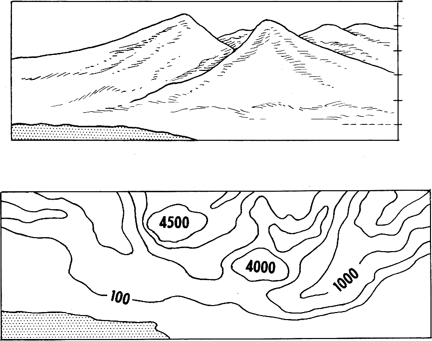


Contouring: Drawing the Shape of the Ground
A traverse gives you the outline of a site. Levelling gives you the height of the points you happened to stand on. Neither tells you the SHAPE of the ground between them — which is what you need to know where water will go, where a building will need cut and fill, and whether a path can be walked.
A contour is a line joining points of equal height. Nobody surveys contours directly; you level a grid of spot heights and then work out where each contour must cross between them, by proportion. The map that results is the single most information-dense drawing in surveying: slope, drainage, volume and visibility are all readable from it.
It is also the rung that makes the water blueprints buildable. A constructed wetland or a drainage run needs to know which way the ground falls, and by how much.
Intermédiaire
2 days
Consignes
1
1
Lay out a grid over the area
Lay out a grid over the area
Set out a square grid of pegs — 5, 10 or 20 metres depending on how broken the ground is — using the right-angle method and a tape. Letter one axis and number the other, so every peg has a name like C4.
Choose the spacing from the SMALLEST feature you care about, not from how much walking you are willing to do. A 20-metre grid cannot see a 5-metre gully, and no amount of careful levelling at the pegs will put it back. The grid is a sampling decision, and it is made before any measurement.
Matériaux pour cette étape :
 Chevilles en bois40 pièces
 Cordeau100 metre
 Kit de fanions et de piquets de repérage1 kit
Outils nécessaires :
 Mètre ruban
 Marteau à panne fendue
2
2
Level every grid point from as few setups as possible
Level every grid point from as few setups as possible
Set the instrument where it can see the most pegs, take a backsight to your benchmark, then read the staff at every visible peg as an intermediate sight.
Intermediate sights are cheap — one instrument setup can produce twenty heights — but they carry no check at all, because nothing closes on them. So move between setups on a proper backsight-and-foresight change point, and close the whole run back to the benchmark at the end. Speed on the intermediates, rigour on the change points.
Outils nécessaires :
 Niveau optique (topographie)
 Mire de nivellement
 Trépied photo
3
3
Write the heights on the plan, at the pegs
Write the heights on the plan, at the pegs
Plot the grid to scale and write each reduced level beside its peg, to the nearest 10 millimetres.
Write them small and consistently placed — always above-right of the point, for example — because you are about to draw lines through this drawing and it must stay readable. Do not round to the nearest 100 millimetres to tidy it up: the interpolation in the next step needs the real figures, and a rounded grid produces contours with false steps in them.
Matériaux pour cette étape :
 Papier millimétré10 pièces
Outils nécessaires :
 Règle
Règle4
4
Interpolate the contour crossings
Interpolate the contour crossings
Between every adjacent pair of pegs, work out where each whole contour value falls, assuming the ground runs straight between them. Mark each crossing with a tick.
The assumption of a straight slope between pegs is exactly that — an assumption, and the only one available. It is why the grid spacing chosen in step 1 governs everything: between two pegs your map is not a measurement, it is a straight line you decided to believe in.
Outils nécessaires :
Règle5
5
Join the ticks, and obey the rules contours cannot break
Join the ticks, and obey the rules contours cannot break
Draw smooth lines through ticks of the same value. Then check them against the rules: contours never cross, never split, never simply stop inside the map, and close on themselves or run off the edge.
They also point UPSTREAM in a valley, forming a V that aims uphill — which is the quickest way to read drainage off a map and the quickest way to spot that you have drawn one backwards. Every one of those rules follows from a contour being a level line on a continuous surface, and a drawing that breaks one has a mistake in it, not an unusual landscape.
6
6
Interpolation, interval and what the map can tell you
Interpolation, interval and what the map can tell you
Chargement du notebook Jupyter…
Outils nécessaires :
RègleMatériaux
4- 40 piècesEspace réservé
- 100 metreEspace réservé
- Espace réservé
- 10 piècesEspace réservé
Outils requis
6- 1 vendor sell this, none ship to you yetEspace réservé
- Espace réservé
- Espace réservé
- Espace réservé
- Espace réservé
- Espace réservé
Blueprints liés
Ces blueprints partagent des connaissances — techniques, matériaux ou principes


CC0 Domaine public
Ce blueprint est publié sous CC0. Vous êtes libre de copier, modifier, distribuer et utiliser ce travail pour tout usage, sans demander la permission.
Soutenez le Maker en achetant des produits via son Blueprint où il perçoit une Commission Maker définie par les Vendeurs, ou créez une nouvelle itération de ce Blueprint et incluez-le comme connexion dans votre propre Blueprint pour partager les revenus.