// Pocket Morse code decoder - ATmega328P-AU, internal 8 MHz, CR2032
// Board: Arduino Pro or Pro Mini, ATmega328P (3.3V, 8MHz) - burn fuses for internal RC (see notes)
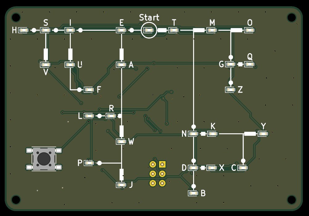
// 27 LEDs charlieplexed on A0..A5 (PC0..PC5), button on D2 (INT0) to GND.
#include <avr/sleep.h>
#include <avr/power.h>
#include <avr/interrupt.h>

// ---------------- timing constants (ms) ----------------
const unsigned long DEBOUNCE_MS       = 20;     // button debounce
const unsigned long DASH_THRESHOLD_MS = 250;    // press shorter = dot, longer = dash
const unsigned long CHAR_GAP_MS       = 700;    // silence that ends a character
const unsigned long BLINK_ON_MS       = 150;    // result blink on time
const unsigned long BLINK_OFF_MS      = 150;    // result blink off time
const uint8_t       BLINK_COUNT       = 3;      // number of result blinks
const unsigned long IDLE_SLEEP_MS     = 30000;  // idle time before power-down

// ---------------- hardware ----------------
const uint8_t BUTTON_PIN = 2;                   // INT0, internal pull-up, active low
const uint8_t LINE_PINS[6] = {A0, A1, A2, A3, A4, A5};  // charlieplex lines CP1..CP6
const uint8_t MAX_CODE_LEN = 4;

struct Node {
  const char *code;   // "" = Start
  char label;
  uint8_t anode;      // index into LINE_PINS
  uint8_t cathode;
};

const Node NODES[] = {
  {"", ' ', 0, 2},   // D1
  {"-", 'T', 2, 0},   // D2
  {".", 'E', 1, 0},   // D3
  {"--", 'M', 2, 1},   // D4
  {"-.", 'N', 5, 1},   // D5
  {".-", 'A', 4, 1},   // D6
  {"..", 'I', 0, 1},   // D7
  {"---", 'O', 1, 2},   // D8
  {"--.", 'G', 2, 4},   // D9
  {"-.-", 'K', 1, 5},   // D10
  {"-..", 'D', 5, 3},   // D11
  {".--", 'W', 1, 4},   // D12
  {".-.", 'R', 3, 1},   // D13
  {"..-", 'U', 0, 4},   // D14
  {"...", 'S', 5, 0},   // D15
  {"--.-", 'Q', 5, 2},   // D16
  {"--..", 'Z', 4, 2},   // D17
  {"-.--", 'Y', 2, 5},   // D18
  {"-.-.", 'C', 5, 4},   // D19
  {"-..-", 'X', 4, 5},   // D20
  {"-...", 'B', 3, 5},   // D21
  {".---", 'J', 4, 3},   // D22
  {".--.", 'P', 3, 4},   // D23
  {".-..", 'L', 1, 3},   // D24
  {"..-.", 'F', 4, 0},   // D25
  {"...-", 'V', 0, 3},   // D26
  {"....", 'H', 3, 0},   // D27
};
const uint8_t NODE_COUNT = sizeof(NODES) / sizeof(NODES[0]);
const int8_t START_NODE = 0;

// ---------------- state ----------------
char seq[MAX_CODE_LEN + 2];
uint8_t seqLen = 0;
bool seqInvalid = false;
bool charPending = false;
bool btnStable = false;          // true = pressed
bool btnLastRaw = false;
unsigned long btnRawChange = 0;
unsigned long pressStart = 0;
unsigned long lastRelease = 0;
unsigned long lastActivity = 0;

void ledsOff() {
  for (uint8_t i = 0; i < 6; i++) {
    pinMode(LINE_PINS[i], INPUT);
    digitalWrite(LINE_PINS[i], LOW);
  }
}

void ledOn(int8_t idx) {
  ledsOff();
  if (idx < 0 || idx >= NODE_COUNT) return;
  uint8_t a = LINE_PINS[NODES[idx].anode];
  uint8_t c = LINE_PINS[NODES[idx].cathode];
  digitalWrite(c, LOW);
  pinMode(c, OUTPUT);
  digitalWrite(a, HIGH);
  pinMode(a, OUTPUT);
}

int8_t findNode(const char *code) {
  for (uint8_t i = 0; i < NODE_COUNT; i++) {
    if (strcmp(NODES[i].code, code) == 0) return i;
  }
  return -1;
}

void blinkNode(int8_t idx) {
  for (uint8_t k = 0; k < BLINK_COUNT; k++) {
    ledsOff();
    delay(BLINK_OFF_MS);
    ledOn(idx);
    delay(BLINK_ON_MS);
  }
  ledsOff();
  delay(BLINK_OFF_MS);
}

bool rawPressed() { return digitalRead(BUTTON_PIN) == LOW; }

// returns +1 on debounced press, -1 on debounced release, 0 otherwise
int8_t pollButton(unsigned long now) {
  bool raw = rawPressed();
  if (raw != btnLastRaw) { btnLastRaw = raw; btnRawChange = now; }
  if (raw != btnStable && (now - btnRawChange) >= DEBOUNCE_MS) {
    btnStable = raw;
    return raw ? 1 : -1;
  }
  return 0;
}

void resetSequence() {
  seqLen = 0;
  seq[0] = 0;
  seqInvalid = false;
  charPending = false;
}

ISR(INT0_vect) {
  EIMSK &= ~_BV(INT0);   // one-shot wake interrupt
}

void waitForRelease() {
  unsigned long t = millis();
  while (true) {
    if (rawPressed()) t = millis();
    if (millis() - t >= DEBOUNCE_MS) break;
  }
  btnStable = false; btnLastRaw = false;
}

void goToSleep() {
  ledsOff();
  set_sleep_mode(SLEEP_MODE_PWR_DOWN);
  cli();
  EICRA &= ~(_BV(ISC01) | _BV(ISC00));   // INT0 on low level (works in power-down)
  EIFR = _BV(INTF0);
  EIMSK |= _BV(INT0);
  sleep_enable();
  sleep_bod_disable();
  sei();
  sleep_cpu();
  sleep_disable();
  EIMSK &= ~_BV(INT0);
  // woken by the button: this press only wakes the board
  waitForRelease();
}

void wakeUp() {
  resetSequence();
  ledOn(START_NODE);
  lastActivity = millis();
}

void setup() {
  ADCSRA = 0;
  power_adc_disable();
  power_spi_disable();
  power_twi_disable();
  power_usart0_disable();
  power_timer1_disable();
  power_timer2_disable();
  ACSR = _BV(ACD);                 // analog comparator off
  DIDR0 = 0x3F;                    // digital input buffers off on PC0..PC5 (outputs only)
  for (uint8_t p = 0; p <= 13; p++) pinMode(p, INPUT_PULLUP);  // unused pins defined
  pinMode(BUTTON_PIN, INPUT_PULLUP);
  ledsOff();
  delay(5);
  btnLastRaw = btnStable = rawPressed();
  wakeUp();
}

void loop() {
  unsigned long now = millis();
  int8_t ev = pollButton(now);

  if (ev == 1) {                         // press
    pressStart = now;
    lastActivity = now;
  } else if (ev == -1) {                 // release: classify
    unsigned long dur = now - pressStart;
    char sym = (dur < DASH_THRESHOLD_MS) ? '.' : '-';
    if (seqLen < MAX_CODE_LEN) {
      seq[seqLen++] = sym;
      seq[seqLen] = 0;
    } else {
      seqInvalid = true;
    }
    int8_t idx = seqInvalid ? -1 : findNode(seq);
    if (idx < 0) { seqInvalid = true; ledsOff(); }
    else ledOn(idx);
    charPending = true;
    lastRelease = now;
    lastActivity = now;
  }

  if (charPending && !btnStable && (now - lastRelease) >= CHAR_GAP_MS) {
    int8_t idx = seqInvalid ? -1 : findNode(seq);
    if (idx >= 0) blinkNode(idx);
    else blinkNode(START_NODE);
    resetSequence();
    ledOn(START_NODE);
    lastActivity = millis();
  }

  if (!charPending && !btnStable && (millis() - lastActivity) >= IDLE_SLEEP_MS) {
    goToSleep();
    wakeUp();
  }
}

 Circuit imprimé1 pièce
 Ordinateur avec l'IDE Arduino
 Microcontrôleur ATmega328P1 pièce
 LED CMS27 pièces
 Résistance CMS7 pièces
 Condensateur céramique CMS3 pièces
 Bouton-poussoir1 pièce
 Support de piles1 pièce
 Pâte à braser (sans plomb)1 pièce
 Fil de soudure1 pièce
 Station de reprise à air chaud
 Fer à souder
 Pince brucelles à pointes fines
 Flux
 Loupe
 Multimètre
 Alcool isopropylique à 99 %
 Programmateur AVR ISP
 Filament PLA1 pièce
 Vis autotaraudeuse4 pièces
 Pile bouton CR20321 pièce
 Imprimante 3D à filament (FDM)
 Pied à coulisse
 Jeu de tournevis de précision