/*
  Pocket Morse decoder - firmware for ATmega328P-AU, internal 8 MHz, CR2032 (3 V)
  Board: Arduino Pro or Pro Mini, ATmega328P (3.3V, 8 MHz)  (fqbn arduino:avr:pro:cpu=8MHzatmega328)
  Fuses for the internal 8 MHz RC oscillator (set once with an ISP programmer):
    lfuse 0xE2, hfuse 0xD9, efuse 0xFF (brown-out detector off to save the coin cell)
  Upload with "Upload Using Programmer" over the 2x3 ISP header.

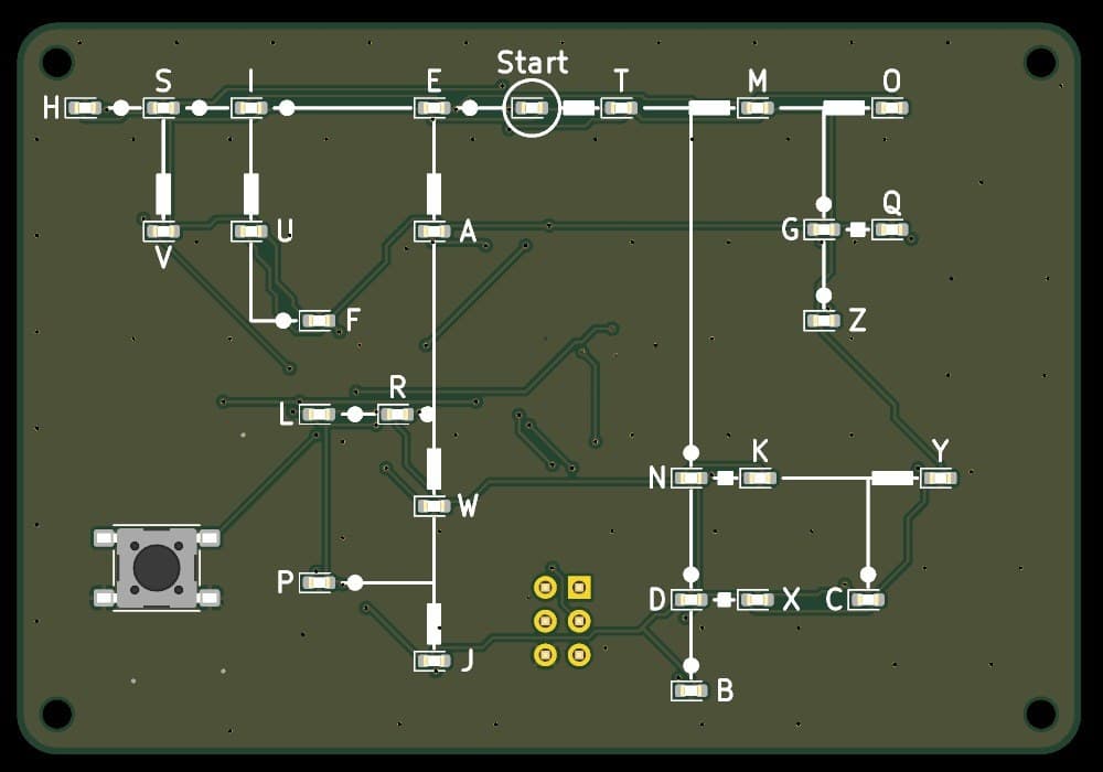
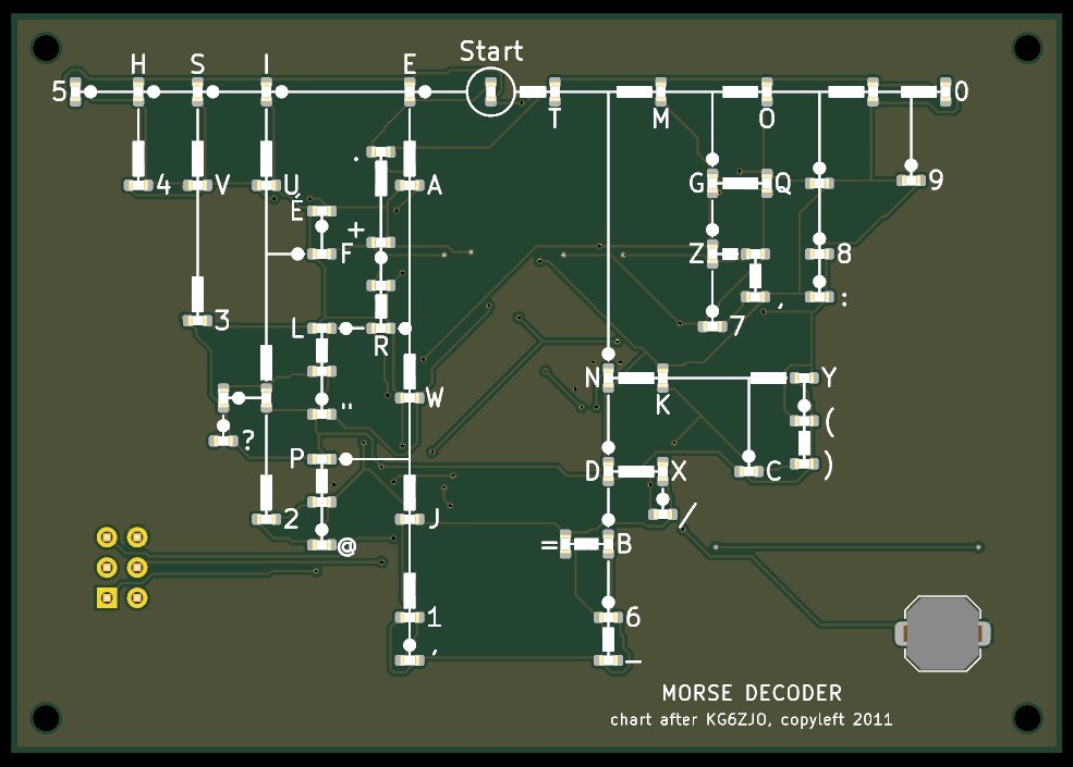
  59 LEDs are charlieplexed on 9 pins (each pin through its own 300 ohm resistor).
  Only one LED is ever lit.  Button on INT0 (D2) to GND, internal pull-up.
*/
#include <avr/sleep.h>
#include <avr/power.h>
#include <avr/pgmspace.h>

// ---------------- timings (milliseconds) ----------------
const unsigned long DASH_THRESHOLD_MS = 250;    // press shorter = dot, longer (or equal) = dash
const unsigned long CHAR_GAP_MS       = 700;    // no press for this long ends the character
const unsigned long IDLE_SLEEP_MS     = 30000;  // no press for this long -> all off, power-down sleep
const unsigned long BLINK_ON_MS       = 150;    // result blink: LED on time
const unsigned long BLINK_OFF_MS      = 150;    // result blink: LED off time
const uint8_t       BLINK_COUNT       = 3;      // number of result blinks
const unsigned long DEBOUNCE_MS       = 20;     // button debounce time

// ---------------- hardware ----------------
const uint8_t BUTTON_PIN = 2;                   // PD2 / INT0
// charlieplex lines L1..L9 -> PC0..PC5, PD0, PD1, PD3
const uint8_t LINE_PIN[9] = {A0, A1, A2, A3, A4, A5, 0, 1, 3};
const uint8_t MAX_CODE_LEN = 7;

struct Node { uint8_t len; uint8_t bits; uint8_t anode; uint8_t cathode; };
// bits: symbol j of the code is bit j (1 = dash). Index 0 is Start.
const Node NODES[] PROGMEM = {
  {0, 0x00, 0, 8},  // D1 S Start
  {1, 0x01, 3, 8},  // D2 - T
  {1, 0x00, 8, 0},  // D3 . E
  {2, 0x03, 3, 6},  // D4 -- M
  {2, 0x01, 6, 5},  // D5 -. N
  {2, 0x02, 0, 3},  // D6 .- A
  {2, 0x00, 8, 1},  // D7 .. I
  {3, 0x07, 3, 7},  // D8 --- O
  {3, 0x03, 6, 7},  // D9 --. G
  {3, 0x05, 5, 6},  // D10 -.- K
  {3, 0x01, 5, 2},  // D11 -.. D
  {3, 0x06, 4, 1},  // D12 .-- W
  {3, 0x02, 1, 7},  // D13 .-. R
  {3, 0x04, 1, 3},  // D14 ..- U
  {3, 0x00, 8, 3},  // D15 ... S
  {4, 0x0F, 3, 5},  // D16 ---- _
  {4, 0x07, 5, 7},  // D17 ---. _
  {4, 0x0B, 7, 6},  // D18 --.- Q
  {4, 0x03, 7, 8},  // D19 --.. Z
  {4, 0x0D, 8, 2},  // D20 -.-- Y
  {4, 0x05, 6, 2},  // D21 -.-. C
  {4, 0x09, 6, 0},  // D22 -..- X
  {4, 0x01, 2, 5},  // D23 -... B
  {4, 0x0E, 0, 1},  // D24 .--- J
  {4, 0x06, 2, 4},  // D25 .--. P
  {4, 0x0A, 1, 2},  // D26 .-.- _
  {4, 0x02, 7, 1},  // D27 .-.. L
  {4, 0x0C, 7, 2},  // D28 ..-- _
  {4, 0x04, 2, 1},  // D29 ..-. F
  {4, 0x08, 3, 4},  // D30 ...- V
  {4, 0x00, 8, 4},  // D31 .... H
  {5, 0x1F, 5, 3},  // D32 ----- 0
  {5, 0x0F, 7, 5},  // D33 ----. 9
  {5, 0x07, 8, 7},  // D34 ---.. 8
  {5, 0x13, 6, 8},  // D35 --..- _
  {5, 0x03, 8, 6},  // D36 --... 7
  {5, 0x0D, 2, 8},  // D37 -.--. (
  {5, 0x09, 0, 6},  // D38 -..-. /
  {5, 0x11, 0, 2},  // D39 -...- =
  {5, 0x01, 5, 0},  // D40 -.... 6
  {5, 0x1E, 1, 5},  // D41 .---- 1
  {5, 0x16, 0, 4},  // D42 .--.- _
  {5, 0x0A, 3, 2},  // D43 .-.-. +
  {5, 0x12, 2, 7},  // D44 .-..- _
  {5, 0x1C, 4, 0},  // D45 ..--- 2
  {5, 0x0C, 7, 4},  // D46 ..--. _
  {5, 0x04, 3, 1},  // D47 ..-.. É
  {5, 0x18, 1, 4},  // D48 ...-- 3
  {5, 0x10, 4, 3},  // D49 ....- 4
  {5, 0x00, 4, 8},  // D50 ..... 5
  {6, 0x07, 8, 5},  // D51 ---... :
  {6, 0x33, 5, 8},  // D52 --..-- ,
  {6, 0x2D, 2, 6},  // D53 -.--.- )
  {6, 0x21, 0, 5},  // D54 -....- -
  {6, 0x1E, 5, 1},  // D55 .----. '
  {6, 0x16, 2, 0},  // D56 .--.-. @
  {6, 0x2A, 3, 0},  // D57 .-.-.- .
  {6, 0x12, 4, 2},  // D58 .-..-. "
  {6, 0x0C, 4, 7},  // D59 ..--.. ?
};
const uint8_t NODE_COUNT = sizeof(NODES) / sizeof(NODES[0]);
const uint8_t START_NODE = 0;
const int8_t  NO_NODE = -1;

volatile bool wokeUp = false;

void allOff() {
  for (uint8_t i = 0; i < 9; i++) {
    pinMode(LINE_PIN[i], INPUT);
    digitalWrite(LINE_PIN[i], LOW);
  }
}

void lightNode(int8_t idx) {
  allOff();
  if (idx < 0 || idx >= NODE_COUNT) return;
  uint8_t a = pgm_read_byte(&NODES[idx].anode);
  uint8_t k = pgm_read_byte(&NODES[idx].cathode);
  digitalWrite(LINE_PIN[k], LOW);
  pinMode(LINE_PIN[k], OUTPUT);
  digitalWrite(LINE_PIN[a], HIGH);
  pinMode(LINE_PIN[a], OUTPUT);
}

int8_t findNode(uint8_t len, uint8_t bits) {
  for (uint8_t i = 0; i < NODE_COUNT; i++) {
    if (pgm_read_byte(&NODES[i].len) == len && pgm_read_byte(&NODES[i].bits) == bits) return i;
  }
  return NO_NODE;
}

bool buttonDown() { return digitalRead(BUTTON_PIN) == LOW; }

// wait until the button state is stable; returns that state
bool debouncedState() {
  bool s = buttonDown();
  unsigned long t = millis();
  while (millis() - t < DEBOUNCE_MS) {
    if (buttonDown() != s) { s = buttonDown(); t = millis(); }
  }
  return s;
}

void blink(int8_t idx) {
  for (uint8_t i = 0; i < BLINK_COUNT; i++) {
    lightNode(idx); delay(BLINK_ON_MS);
    allOff();       delay(BLINK_OFF_MS);
  }
}

void wakeISR() {
  detachInterrupt(digitalPinToInterrupt(BUTTON_PIN));
  wokeUp = true;
}

void goToSleep() {
  allOff();
  while (debouncedState()) {}              // make sure the button is released
  uint8_t adcsra = ADCSRA;
  ADCSRA = 0;                               // ADC off
  set_sleep_mode(SLEEP_MODE_PWR_DOWN);
  noInterrupts();
  wokeUp = false;
  EIFR = bit(INTF0);
  attachInterrupt(digitalPinToInterrupt(BUTTON_PIN), wakeISR, LOW);  // level interrupt wakes from power-down
  sleep_enable();
  sleep_bod_disable();
  interrupts();
  sleep_cpu();
  sleep_disable();
  ADCSRA = adcsra;
  while (debouncedState()) {}              // the waking press only wakes the board
}

uint8_t codeLen = 0;
uint8_t codeBits = 0;
bool    codeValid = true;
unsigned long lastActivity = 0;

void resetToStart() {
  codeLen = 0; codeBits = 0; codeValid = true;
  lightNode(START_NODE);
}

void setup() {
  for (uint8_t p = 4; p <= 13; p++) pinMode(p, INPUT_PULLUP);  // unused pins: no floating inputs
  pinMode(BUTTON_PIN, INPUT_PULLUP);
  allOff();
  power_spi_disable();
  power_twi_disable();
  power_usart0_disable();
  resetToStart();
  lastActivity = millis();
}

void loop() {
  unsigned long now = millis();

  if (debouncedState()) {                    // button pressed
    unsigned long pressStart = millis();
    while (debouncedState()) {}
    unsigned long pressLen = millis() - pressStart;
    bool dash = pressLen >= DASH_THRESHOLD_MS;
    if (codeValid && codeLen < MAX_CODE_LEN) {
      if (dash) codeBits |= (1 << codeLen);
      codeLen++;
      int8_t n = findNode(codeLen, codeBits);
      if (n == NO_NODE) { codeValid = false; allOff(); }
      else lightNode(n);
    } else {
      codeValid = false; allOff();
    }
    lastActivity = millis();
    return;
  }

  if (codeLen > 0 && now - lastActivity >= CHAR_GAP_MS) {   // end of character
    if (codeValid) blink(findNode(codeLen, codeBits));
    else blink(START_NODE);
    resetToStart();
    lastActivity = millis();   // idle time counts from the end of the character
    return;
  }

  if (codeLen == 0 && now - lastActivity >= IDLE_SLEEP_MS) {
    goToSleep();
    resetToStart();            // on wake light Start
    lastActivity = millis();
  }
}

 Circuit imprimé1 pièce
 Ordinateur avec l'IDE Arduino
 Microcontrôleur ATmega328P1 pièce
 LED CMS59 pièces
 Résistance CMS10 pièces
 Condensateur céramique CMS3 pièces
 Bouton-poussoir1 pièce
 Support de piles1 pièce
 Pâte à braser (sans plomb)1 pièce
 Fil de soudure1 pièce
 Station de reprise à air chaud
 Fer à souder
 Pince brucelles à pointes fines
 Flux
 Loupe
 Multimètre
 Alcool isopropylique à 99 %
 Programmateur AVR ISP
 Filament PLA1 pièce
 Vis autotaraudeuse4 pièces
 Pile bouton CR20321 pièce
 Imprimante 3D à filament (FDM)
 Pied à coulisse
 Jeu de tournevis de précision