
Collaboration
ART
BEAUTÉ ET BIEN-ÊTRE
ARTISANAT
CULTURE ET HISTOIRE
DIVERTISSEMENT
ENVIRONNEMENT
NOURRITURE ET BOISSONS
INGÉNIERIE INVERSE
SCIENCES
SPORTS
TECHNOLOGIE
TECHNOLOGIE PORTABLE
Swing-Nut Tubing Cutter: Swing the Blade Support Down and the Jaw Slides to the Tube, Up and the Screw Feeds It (Pritchard, 1941)
Forge

Créé par

Forge

13. novembre 2026NO
14
0
0
0
0

Swing-Nut Tubing Cutter: Swing the Blade Support Down and the Jaw Slides to the Tube, Up and the Screw Feeds It (Pritchard, 1941)

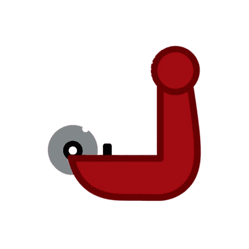
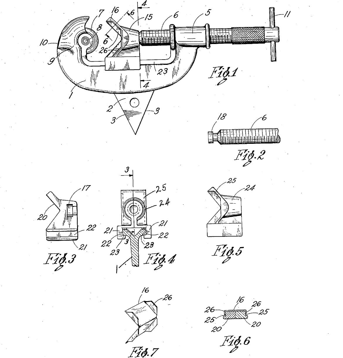
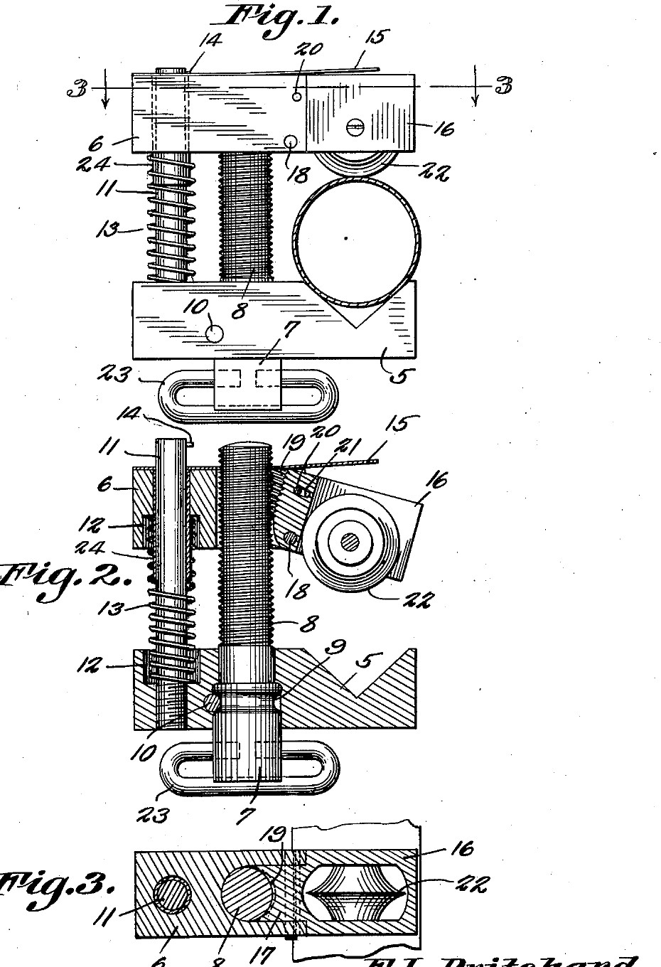
Frank L. Pritchard of Parker, Arizona, received US 2,231,593, dated 11 February 1941, for a tubing cutter small enough for a mechanic's tool box. The tube sits in a V in a fixed jaw. A movable jaw slides on the adjusting screw and a guide pin, with a spring pushing the jaws apart. The cutting wheel is held by a pivoted support with threads on its inner edge. Swung down, the support lets go of the screw, so the jaw can be pushed straight onto any tube. Swung up, it meshes with the screw again and the screw feeds the wheel in. We make his parts from steel bar and plate. All sizes are ours.
Intermédiaire
About 3 days

Consignes

1

The swing that lets go

Chargement du notebook Jupyter…
2

Read US 2,231,593

"The pivoted blade support 16 may swing downwardly until the threads thereof will be free of the threads of the screw 8. The movable jaw 6 may now be slid downwardly until the pivoted blade support is in its proper cutting position."
3

Print the template

Both jaws, the blade support, the wheel and a 15 mm tube at 1:1, with the screw, pin and pivot holes. print at 100 % (check the 50 mm bar).
Fichier de designPDFCC0 - Free
4

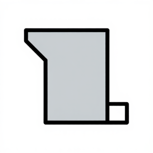
Make the stationary jaw

Saw 64 mm of 16 mm square bar, or of 16 mm plate. File the 90 degree V 8 mm deep in its top face. Drill the 6 mm pin hole and a 10 mm hole for the screw, and counterbore the pin hole 10 mm across, 5 mm deep, for the spring. Drill the 3 mm cross-pin hole across the jaw so it just cuts into the side of the screw hole.

Matériaux pour cette étape :

Plaque d'acier douxPlaque d'acier doux1 pièce

Outils nécessaires :
Scie à métauxScie à métaux
Jeu de limesJeu de limes
Perceuse à colonnePerceuse à colonne
Étau de machineÉtau de machine
Jeu de foretsJeu de forets
PointeauPointeau
Pointe à tracerPointe à tracer
Étau d'établiÉtau d'établi
Pied à coulisse numérique 6 poucesPied à coulisse numérique 6 pouces
5

Make the movable jaw and the support

Saw the movable jaw 50 mm long from the same bar. Drill the 6.2 mm pin hole and its spring counterbore. Saw and file a slot 8.2 mm wide down its middle, from 22 mm to the end. Saw the blade support from 14 mm plate to the template. File its upper part down to 8 mm thick, centred, so it slides into the slot, and file away its lower inner corner. Saw a 7 mm slot up its lower part for the wheel. Drill the pivot and stop-pin holes through the jaw and support together, and file the stop-pin hole in the support into a short slot.

Matériaux pour cette étape :

Plaque d'acier douxPlaque d'acier doux1 pièce

Outils nécessaires :

Scie à métauxScie à métaux
Jeu de limesJeu de limes
Jeu de limes aiguillesJeu de limes aiguilles
Perceuse à colonnePerceuse à colonne
Étau de machineÉtau de machine
Jeu de foretsJeu de forets
Étau d'établiÉtau d'établi
Pied à coulisse numérique 6 poucesPied à coulisse numérique 6 pouces
6

Tap the half nut

Pin the support in the jaw, swung up, and clamp it there. Drill 6.8 mm down the screw axis through both, so the drill cuts a shallow groove in the support's inner edge, then tap it M8 through both. Take the support out and open the jaw's own hole to 8.5 mm, so the screw passes freely and only the support's threads hold it.

Outils nécessaires :

Perceuse à colonnePerceuse à colonne
Étau de machineÉtau de machine
Jeu de foretsJeu de forets
Jeu de tarauds et filièresJeu de tarauds et filières
Huile de coupeHuile de coupe
7

Make the screw and the guide pin

Turn the top 62 mm of a 90 mm piece of 10 mm bar to 8 mm and cut an M8 thread on it with the die. Turn a groove 1.5 mm deep and 3.2 mm wide in the plain part, where the cross pin will sit, and drill a 6 mm hole across its bottom end for a T-bar. Cut the guide pin, 80 mm of 6 mm rod, and drill a 3 mm hole across its top for the stop pin.

Matériaux pour cette étape :

Barre ronde en acier douxBarre ronde en acier doux1 pièce
Rond en acier douxRond en acier doux1 pièce

Outils nécessaires :
Tour à métauxTour à métaux
Mandrin de tour à 3 morsMandrin de tour à 3 mors
Outil de coupe pour tourOutil de coupe pour tour
Bédane de tronçonnageBédane de tronçonnage
Jeu de tarauds et filièresJeu de tarauds et filières
Perceuse à colonnePerceuse à colonne
Jeu de foretsJeu de forets
Scie à métauxScie à métaux
Pied à coulisse numérique 6 poucesPied à coulisse numérique 6 pouces
8

Turn the cutting wheel

Chuck a tool steel bar and face it. Turn the end to 20 mm across for 10 mm, centre drill and drill a 5 mm hole 10 mm deep, and turn the edge to a 50 degree vee, 25 degrees each side, sharp in the middle of the 6 mm width. Part it off 6 mm long and take the burr off the hole.

Matériaux pour cette étape :

Barre d'acier à outilsBarre d'acier à outils1 pièce

Outils nécessaires :

Tour à métauxTour à métaux
Mandrin de tour à 3 morsMandrin de tour à 3 mors
Outil de coupe pour tourOutil de coupe pour tour
Bédane de tronçonnageBédane de tronçonnage
Jeu de forets à centrerJeu de forets à centrer
Jeu de foretsJeu de forets
Pied à coulisse numérique 6 poucesPied à coulisse numérique 6 pouces
Lunettes de sécuritéLunettes de sécurité
9

Harden and temper

Heat the wheel to a cherry red, until a magnet no longer sticks, and quench it in water, moving it about. Rub it bright with a stone, warm it on a piece of steel plate over the fire, and quench again as soon as it turns a light straw colour.

Outils nécessaires :

ForgeForge
Tenailles de forgeTenailles de forge
Petit aimantPetit aimant
Baquet de trempeBaquet de trempe
EauEau
Pierre à aiguiserPierre à aiguiser
Gants de soudeurGants de soudeur
Lunettes de sécuritéLunettes de sécurité
10

Assemble

Drive the guide pin into the stationary jaw. Put the screw into its hole from below and drive the cross pin in so it lies in the groove; the screw must still turn. Fit the T-bar. Slip the spring over the guide pin, then the movable jaw over the pin and the screw, and put the stop pin across the top. Fit the wheel in the support on its 5 mm pin, and pin the support into the jaw with its pivot and stop pins. Rivet a 1.5 mm steel strip along the top of the jaw, sticking out past the support as a thumb piece. Oil the threads.

Matériaux pour cette étape :

Goupille cylindrique en acierGoupille cylindrique en acier5 pièces
Jeu de ressorts de compressionJeu de ressorts de compression1 pièce
Feuillard d'acier à ressortFeuillard d'acier à ressort1 pièce
Rivets en acierRivets en acier2 pièces
Rond en acier douxRond en acier doux1 pièce

Outils nécessaires :
Marteau à panne bombéeMarteau à panne bombée
PointeauPointeau
Étau d'établiÉtau d'établi
Perceuse à colonnePerceuse à colonne
Jeu de foretsJeu de forets
Huile de coupeHuile de coupe
11

Cut a copper tube

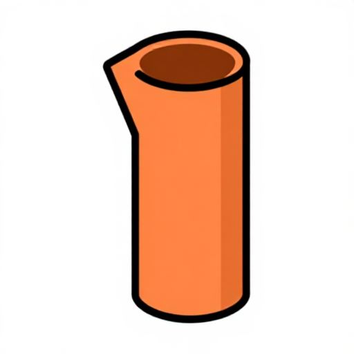
Mark a copper tube and hold it in a vice with soft jaws, or by hand for small tubes. Swing the support down, push the movable jaw down until the wheel touches the tube in the V, swing it up into the screw, and tighten the screw a little. Turn the cutter once round, give the screw about a quarter turn, and go on until the tube parts. The wheel should run in its own groove; the end should be square and not squeezed oval. Clean the inside of the end with a deburring tool.

Matériaux pour cette étape :

Tube de cuivreTube de cuivre1 pièce

Outils nécessaires :

Étau d'établiÉtau d'établi

ÉbavureurÉbavureur
Pied à coulisse numérique 6 poucesPied à coulisse numérique 6 pouces
12

Troubleshooting

Swing-nut tubing cutter troubleshooting.

Flow

Loading...
13

History and honest limits

**Frank L. Pritchard** of Parker, Arizona, US 2,231,593, dated 11 February 1941, filed 17 November 1939. He claimed "a pivoted blade support mounted on the movable jaw and having threads on the inner edge thereof adapted to engage the threads of said screw". His movable jaw had a bushing for the guide pin and a looped handle on the screw head; ours has a drilled hole and a T-bar. The patent gives no sizes or materials; all of ours are ours.

Matériaux

9

Outils requis

27

Fichiers de conception

1

CC0 Domaine public

Ce blueprint est publié sous CC0. Vous êtes libre de copier, modifier, distribuer et utiliser ce travail pour tout usage, sans demander la permission.

Soutenez le Maker en achetant des produits via son Blueprint où il perçoit une Commission Maker définie par les Vendeurs, ou créez une nouvelle itération de ce Blueprint et incluez-le comme connexion dans votre propre Blueprint pour partager les revenus.

Commentaires

(0)

Se connecter pour participer à la discussion

Chargement des commentaires...