Collaboration
ART
BEAUTÉ ET BIEN-ÊTRE
ARTISANAT
CULTURE ET HISTOIRE
DIVERTISSEMENT
ENVIRONNEMENT
NOURRITURE ET BOISSONS
INGÉNIERIE INVERSE
SCIENCES
SPORTS
TECHNOLOGIE
TECHNOLOGIE PORTABLE
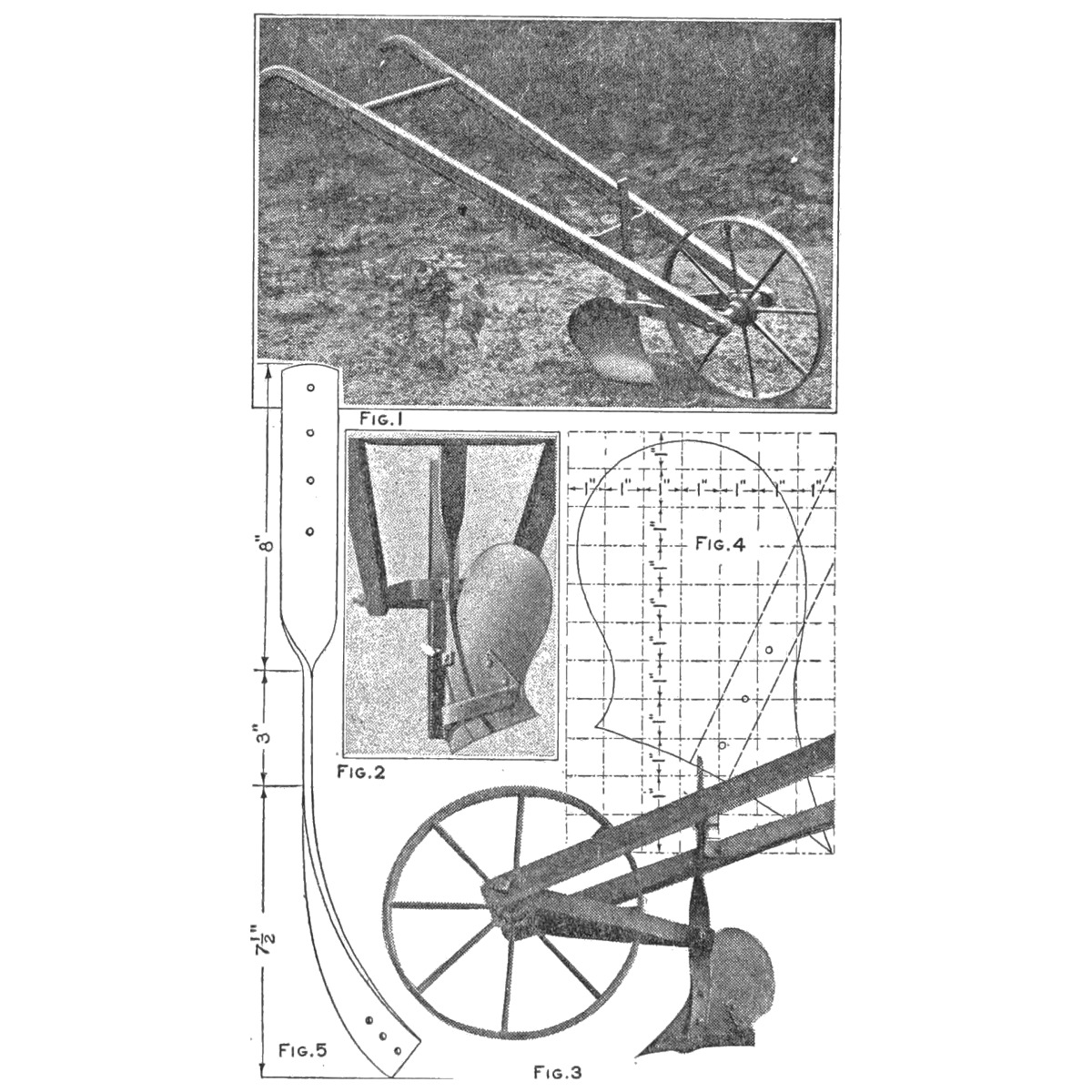


Garden Hand Plow From Scrap: Wheelbarrow Wheel, Ripped Spruce Handles and a Shovel-Blade Moldboard (Boy Mechanic, 1919)
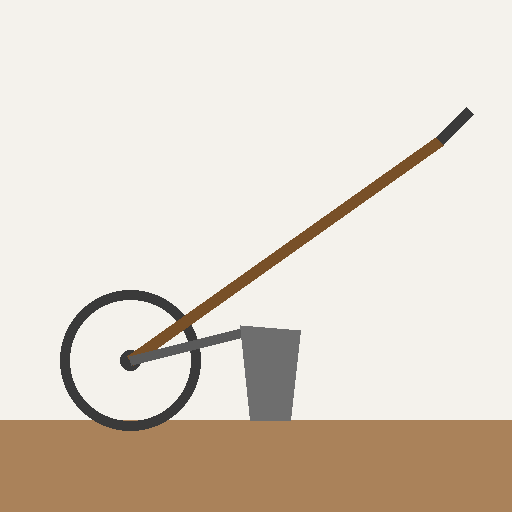
T. T. Sturgeon's hand plow from The Boy Mechanic, Book 3 (1919), "worth about $5 at an outlay of 25 cents": a 16 in wheelbarrow wheel, handles ripped from one spruce strip, iron-strap braces, an adjustable vertical strap, and a moldboard and share cut from an old shovel blade to his grid pattern.
Intermédiaire
About 1 day
Consignes
1
1
His cut list in centimetres
His cut list in centimetres
Chargement du notebook Jupyter…
2
2
Read The Boy Mechanic, Book 3
Read The Boy Mechanic, Book 3
"The labor of spading a garden of even moderate size is sufficient to warrant the person who undertakes the job in making a hand plow like that shown in the illustration."
3
3
Make the handles
Make the handles
Mark both handles on a 7/8 by 4 in spruce strip 5 ft long, one curved grip at each end on opposite edges. Cut the curves with a keyhole saw, then rip the board into the two handles; smooth them and trim the grips with a sharp knife. Cut a section of broomstick for the upper brace.
Matériaux pour cette étape :
 Planche de bois dur1 pièce
 Balai1 pièce
Outils nécessaires :
 Scie à chantourner
 Scie à refendre
 Couteau à cuir
 Crayon
4
4
Make the iron parts
Make the iron parts
Lower brace: iron 1/4 by 1-1/4 by 12 in, drilled for 1/4 in bolts, bent at right angles 1-1/2 in from each end, with a 1/4 in hole at the middle. Vertical support: 1/4 by 1-1/4 by 18 in, four 1/4 in adjusting holes 1 in apart at the top, three 1/4 in holes at the bottom for the moldboard, and a 5/16 in hole at the 7-1/2 in mark. Two braces 14 in long of 1/4 by 1-1/4 in, a 3/8 in hole at the front of each for the 3/8 by 10 in axle bolt and a 5/16 in hole at the other end, each 1 in from the end. Landside: 1/8 by 3/4 by 12 in.
Matériaux pour cette étape :
 Plat en acier doux3 pièces
Outils nécessaires :
 Scie à métaux
 Chignole à main
 Étau d'établi
 Marteau
 Limes (lime à main)
 Mètre ruban
5
5
Cut the moldboard
Cut the moldboard
Draw his moldboard (Fig. 4) on cardboard ruled in 1 in squares, tracing the outline square by square, and mark the bolt holes. Trace it on an old shovel blade, using the thickest part for the point of the share. Cut it out, smooth the edges and sharpen the cutting edge. Drill for 1/4 in bolts to the vertical strap and 3/16 in bolts to the landside.
Matériaux pour cette étape :
 Pelle1 pièce
 Gabarits en carton1 pièce
Outils nécessaires :
CrayonScie à métaux Meuleuse d'angleLimes (lime à main)Chignole à main
6
6
Shape and assemble
Shape and assemble
Curve the moldboard and fit it to the supports as in Figs. 1-3. Bend the 12 in landside strip under the moldboard and bolt it on. Assemble on the 16 in wheel and 3/8 in axle bolt, with wheel and landside in line (Fig. 2) and the landside's rear edge raised slightly (Fig. 3); set the vertical strap's height for the operator in its adjusting holes. Paint the plow and oil the smoothed cutting parts.
Matériaux pour cette étape :
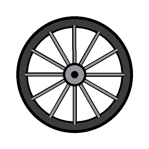 Roue de brouette1 pièce
 Boulon de carrosserie6 pièces
 Écrou hexagonal6 pièces
 Rondelle plate6 pièces
 Peinture à l'huile1 pièce
 Huile de machine1 pièce
Outils nécessaires :
Étau d'établiMarteau Brosse large
7
7
Troubleshooting
Troubleshooting
Garden plow troubleshooting.
Flow
Loading...
8
8
History and honest limits
History and honest limits
From "Garden Plow Made of Pick-Up Material" by T. T. Sturgeon, in **The Boy Mechanic, Book 3**, Popular Mechanics, 1919 (Project Gutenberg 71856; checked on the archive.org scan boymechanic0003unse, pp. 227-228). The moldboard shape is his Fig. 4 grid. The keyhole saw is a coping saw here; the tools and metric figures are ours.
Matériaux
11- 1 pièceEspace réservé
- 1 pièceEspace réservé
- 3 piècesEspace réservé
- 1 pièceEspace réservé
- 1 pièceEspace réservé
- 1 pièceEspace réservé
- 6 piècesEspace réservé
- 6 piècesEspace réservé
- 6 piècesEspace réservé
- 1 pièceEspace réservé
- 1 pièceEspace réservé
Outils requis
12- Espace réservé
- Espace réservé
- Espace réservé
- 1 vendor sell this, none ship to you yetEspace réservé
- Espace réservé
- Espace réservé
- Espace réservé
- Espace réservé
- Espace réservé
- 1 vendor sell this, none ship to you yetEspace réservé
- 1 vendor sell this, none ship to you yetEspace réservé
- Espace réservé
Ce plan fabrique
Blueprints liés
Ces blueprints partagent des connaissances — techniques, matériaux ou principes
CC0 Domaine public
Ce blueprint est publié sous CC0. Vous êtes libre de copier, modifier, distribuer et utiliser ce travail pour tout usage, sans demander la permission.
Soutenez le Maker en achetant des produits via son Blueprint où il perçoit une Commission Maker définie par les Vendeurs, ou créez une nouvelle itération de ce Blueprint et incluez-le comme connexion dans votre propre Blueprint pour partager les revenus.