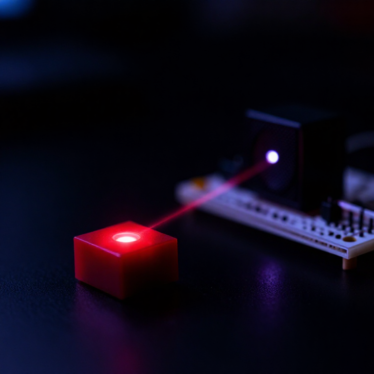


The Laser Communicator
Sound can travel on a beam of light, and the circuit that does it is almost embarrassingly small. Vary the brightness of a light in step with an audio signal, point it at a light-sensitive component, and turn the resulting varying current back into sound. There is no radio, no modulation scheme, no protocol — just brightness carrying a waveform.
The reason it works is that a laser diode's optical output tracks its drive current closely and quickly. Feed it a bias current so it sits at half brightness, superimpose the audio, and the beam flickers at audio frequencies. Your eye sees a steady dot, because it averages anything above a few tens of hertz — but a photodiode or a solar cell does not average, and it delivers the waveform straight back.
Alexander Graham Bell got there in 1880, and considered it his greatest invention — greater, he said, than the telephone. He and Charles Sumner Tainter built the photophone on 19 February 1880, and on 21 June transmitted clear speech about 213 metres on plain sunlight, modulated by a vibrating mirror. The receiver was a selenium cell, whose resistance falls when light hits it. The master patent is US 235,199, issued December 1880.
It went nowhere for a century, for one reason you will rediscover in step 6. Build it and find out.
Consignes
Build the receiver first
Build the receiver first
Wire a light-dependent resistor in series with a resistor across a supply, and take the audio out from their junction into an amplifier and small speaker.
Wave your hand over the LDR.
Expect a thump from the speaker.
Build the receiver before the transmitter — a receiver you have already proved responds to light changes turns the next step into a test rather than a mystery with two possible faults.
Matériaux pour cette étape :
 Photorésistance LDR1 paquet
 Breadboard - Classic1 pièce
Outils nécessaires :
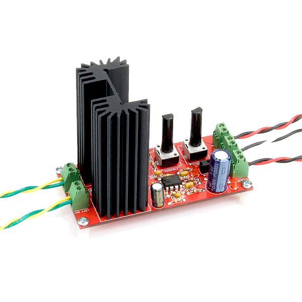 Audio Amplifier Kit - STA540
 Mini haut-parleur 8 ohms 2 W
Prove the receiver hears the mains
Prove the receiver hears the mains
Point the receiver at a mains-powered lamp in a dark room and listen.
Expect a steady hum — the lamp is flickering at twice the mains frequency and your ear cannot see it but the LDR can.
Try a torch, a phone screen and a fluorescent tube and compare.
You have just built an instrument that makes invisible light modulation audible, before transmitting anything at all.
Bias the laser, then add audio
Bias the laser, then add audio
Drive a laser diode module through a current-limiting resistor so it sits at roughly half its normal brightness. Couple an audio source into the drive through a capacitor so the audio adds to and subtracts from that bias.
Never remove the current limit.
The bias is what makes it linear. Without it the negative half of every waveform simply switches the laser off, and speech comes back as a distorted rasp.
Matériaux pour cette étape :
 Jeu de modules à diode laser1 jeu
Outils nécessaires :
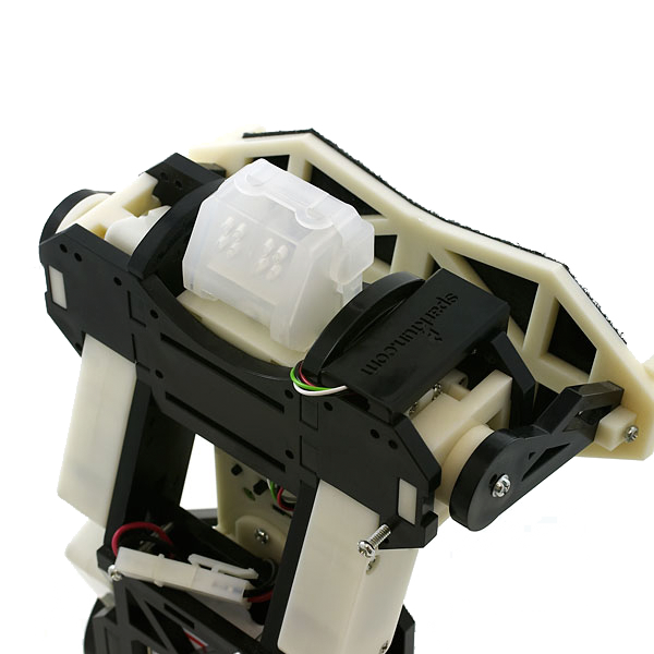 Laser Module Mount
Align, and hear it
Align, and hear it
Point the beam at the LDR across a short bench distance, in a dim room, and adjust until the spot sits squarely on the sensitive surface.
Play music through the transmitter.
Expect recognisable audio, and expect it to disappear entirely the moment the spot drifts off.
Alignment is not a setup nicety, it is the link. This is a point-to-point line-of-sight system with no tolerance at all.
Measure how far it goes, and what breaks it
Measure how far it goes, and what breaks it
Increase the distance in steps, recording the greatest distance at which speech stays intelligible. Then, at a working distance, interrupt the beam with paper, a hand, glass, and finally by breathing steam across it.
Expect total loss from anything opaque, partial loss from steam, and near-nothing from clear glass.
Record the distance at which noise starts to win.
Outils nécessaires :
 Mètre ruban
Find the reason it lost to radio
Find the reason it lost to radio
Take it outside, or in front of a bright window, and try again.
Expect performance to collapse.
The receiver cannot distinguish your modulated beam from a large steady background, and every bit of ambient light adds noise while adding no signal.
That, plus needing a clear straight line and precise aim, is exactly why Bell's photophone was a dead end for a century — and why the technology returned only when the beam could be put inside a glass fibre where nothing else gets in.
History & Context
History & Context
Bell rated the photophone above the telephone, and said so. He and Charles Sumner Tainter made it work on 19 February 1880 in Bell's Washington laboratory, and on 21 June 1880 Tainter stood on the roof of the Franklin School and spoke to Bell about 213 metres away, using nothing but sunlight reflected off a mirror that was made to vibrate by his voice. The receiver used crystalline selenium, whose electrical resistance falls as illumination rises — the same principle as the LDR in step 1. The master patent, Apparatus for Signaling and Communicating, is US 235,199, issued in December 1880.
It was wireless communication, thirteen years before Marconi, and it failed commercially for reasons that had nothing to do with the idea. It needed an unobstructed straight line; it stopped working in fog, rain, cloud or dust; it needed accurate aiming at both ends; and it was drowned by ambient daylight — exactly the four failures you can reproduce on a bench in twenty minutes. Radio waves have none of those problems, and once they arrived, optical communication had no argument.
What changed was the fibre, not the light. Putting the beam inside a glass waveguide removes every one of the photophone's objections at a stroke: the path is fixed, nothing can interrupt it, no ambient light gets in, and aiming is done once at manufacture. Combined with the laser as a coherent, fast-modulating source, that turned Bell's dead end into the technology carrying essentially all long-distance data today. The photophone was not wrong; it was missing a pipe.
Free-space optics is still in use, for the same reasons and against the same limits. Building-to-building laser links, ship-to-ship signalling, satellite crosslinks and consumer infrared remotes are all direct descendants. Satellite laser links are enjoying a resurgence precisely because in space there is no weather and no atmosphere — the photophone's ideal environment, four hundred kilometres up.
🔴 Laser safety, and it is not optional. Use the lowest-power visible module you can (a class 2 pointer-grade device), and treat it as if it will find an eye, because eventually it will. Never look into the beam or its reflection, never aim along eye level, and never point one at a person, a vehicle, or anything in the sky — aiming a laser at an aircraft is a serious criminal offence in most countries. Set the bench so the beam terminates on a matt dark surface. Take particular care with mirrors and glass, which produce reflections you did not plan. Infrared modules are worse, not better, because there is no visible spot and no blink reflex — stick to visible.
Matériaux
3- 1 paquetEspace réservé
- Breadboard - Classic10 % de commission1 pièce€8.37
- Espace réservé
Outils requis
4- Audio Amplifier Kit - STA54010 % de commission€23.82
- Espace réservé
- Laser Module Mount10 % de commission€4.41
- 1 vendor sell this, none ship to you yetEspace réservé
Matériaux des Blueprints connectés
Blueprints liés
Ces blueprints partagent des connaissances — techniques, matériaux ou principes

CC0 Domaine public
Ce blueprint est publié sous CC0. Vous êtes libre de copier, modifier, distribuer et utiliser ce travail pour tout usage, sans demander la permission.
Soutenez le Maker en achetant des produits via son Blueprint où il perçoit une Commission Maker définie par les Vendeurs, ou créez une nouvelle itération de ce Blueprint et incluez-le comme connexion dans votre propre Blueprint pour partager les revenus.