هنر
زیبایی و سلامت
صنایع دستی
فرهنگ و تاریخ
سرگرمی
محیط زیست
غذا و نوشیدنی
مهندسی معکوس
علوم
ورزش
فناوری
پوشیدنیها
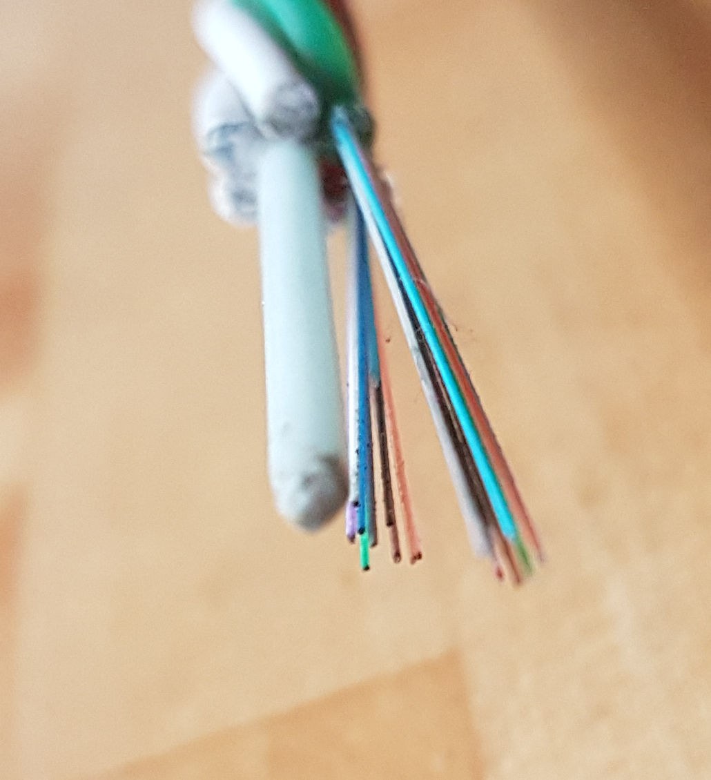
Low-Loss Optical Fibre
Guiding light along a stream of water was a parlour trick by 1842, and bundles of glass fibres were carrying images inside patients by the 1950s. Nobody thought of it as a communications medium, because the best optical glass of the day lost about 1000 decibels per kilometre. Twenty metres of it passes nothing at all.
In July 1966 Charles Kao and George Hockham, at Standard Telecommunication Laboratories in Harlow, published a paper making a claim rather than a device. They had measured the loss carefully and argued that almost none of it was intrinsic to glass. It was IMPURITY absorption, chiefly from iron. Take the transition metals down to parts per billion and the loss should fall below 20 dB per kilometre — the figure at which a fibre beats a copper cable. It was a materials problem, not a physics problem, and materials problems get solved.
It took four years. In 1970 Robert Maurer, Donald Keck and Peter Schultz at Corning made a titania-doped fused silica fibre at 17 dB/km, and by 1972 a germania-doped one at 4 dB/km. Modern single-mode fibre reaches about 0.19 dB/km at 1550 nm — a factor of five thousand better than the glass Kao started from. Kao received the Nobel Prize in Physics in 2009.
MEASURED HONESTLY. Nobody makes 0.2 dB/km glass on a bench. What you will do is the reference measurement itself: a cutback on plastic optical fibre, which is cheap, cuts with a razor blade, and loses about 0.2 dB per METRE — a thousand times worse than silica, for a completely different reason. Measuring the bad fibre properly is how you understand what the good one costs.
متوسط
4 hours
دستورالعملها
1
1
Total internal reflection and the acceptance cone
Total internal reflection and the acceptance cone
Do the refraction measurement first if you have not. A fibre is Snell's law applied twice: a core of index n1 surrounded by a cladding of slightly lower index n2, and any ray striking the boundary beyond the critical angle is reflected with no loss at all.
Two numbers follow directly. The critical angle, sin(theta_c) = n2/n1. And the numerical aperture, NA = sqrt(n1^2 - n2^2), which is the sine of the half-angle of the cone the fibre will accept at its end face.
For SMF-28 the index difference between core and cladding is only about 0.36 %, giving an NA near 0.14 and an acceptance half-angle of about 8 degrees. That tiny difference is deliberate: a bigger NA would collect more light and would also let more modes propagate.
ابزارهای مورد نیاز:
 کیت میز نوری
 اشارهگر لیزری
2
2
Cut and launch into plastic optical fibre
Cut and launch into plastic optical fibre
Cut a 10 m length of 1 mm PMMA fibre. The end face is the whole measurement, so cut it properly: hold the fibre against a hard flat surface and press a fresh razor blade straight down in one motion. Do not saw and do not use side cutters, which crush the core.
Inspect the face with the hand lens. It should be flat, clear, and square to the axis. A chipped or angled face throws a couple of decibels away before the light even enters, and it will not do so repeatably.
Wipe both faces with isopropyl alcohol on a lint-free wipe. Butt the input face against the laser module, hold it with tape, and read the output on the photodiode. Note the reading. Do not disturb the launch end again for the rest of this measurement.
مواد مورد نیاز این مرحله:
 دستهٔ فیبر نوری10 متر
 ایزوپروپیل الکل ۹۹ ٪50 میلیلیتر
ابزارهای مورد نیاز:
 برندهٔ فیبر نوری
 ذرهبین دستی ۱۰ برابر
 مجموعهٔ ماژول دیود لیزری
 فوتودیود (BPW34)
 مولتیمتر دیجیتال درجهٔ آزمایشگاهی
 کولیس دیجیتال ۶ اینچی
3
3
Run the cutback
Run the cutback
Record the received power. Then cut 2 m off the FAR end, re-cut that face cleanly, and record again. Repeat down to 1 m, giving six points.
Cutting the far end rather than the launch end is deliberate and is the opposite of the formal standard, which cuts near the launch. Either works provided the LAUNCH is never disturbed, and for a hand-held butt joint the launch is by far the most fragile part of the setup.
Convert each reading to dBm and plot against length. The slope is the attenuation in dB per metre, and every fixed loss — the launch, the detector coupling, the source power — sits in the intercept where it cannot contaminate the answer. That separation is the whole point of a cutback.
While the fibre is still connected, wrap it once around a pencil and watch the power drop. That is bend loss: past the critical angle the guided ray is no longer guided.
ابزارهای مورد نیاز:
برندهٔ فیبر نوریفوتودیود (BPW34)مولتیمتر دیجیتال درجهٔ آزمایشگاهیمجموعهٔ ماژول دیود لیزری4
4
Decibels, the loss spectrum, and the V number
Decibels, the loss spectrum, and the V number
در حال بارگذاری دفترچهٔ Jupyter…
ابزارهای مورد نیاز:
 رایانهٔ رومیزی
5
5
Compendium: what purity bought, and what it cost
Compendium: what purity bought, and what it cost
WHAT KAO ACTUALLY CLAIMED. Not a fibre — a number, and an argument about where the loss came from. He and Hockham split the measured attenuation into scattering, which follows a known 1/lambda^4 law and is small, and absorption, which was enormous and tracked the transition-metal content. The conclusion: iron, copper, chromium, nickel and vanadium had to come down to parts per BILLION. No bulk melt had ever reached that, and none could, because the crucible itself contaminates the melt.
WHY VAPOUR DEPOSITION WAS THE ANSWER. If you cannot purify a melt, do not make one. Silicon and germanium chlorides distil to extreme purity and are volatile; the chlorides of the offenders are far less so. Build the glass out of vapour and the impurities stay in the bottle. That is the next blueprint, and it is a direct consequence of this one.
THE THREE WINDOWS. 850 nm came first because GaAs lasers and silicon detectors already worked there; about 2 dB/km. 1310 nm next, because silica's material dispersion passes through zero there so pulses stop spreading; about 0.35 dB/km. 1550 nm is the loss minimum at about 0.19 dB/km, awkward at first because dispersion is high — until dispersion compensation solved that and the erbium amplifier at the end of this batch made 1550 nm the only wavelength anyone cared about.
THE SIBLING, MEASURED. Plastic optical fibre: 1 mm core, NA 0.5, cuts with a razor, couples to a bare LED, terminates by hand, pennies a metre, 200 dB/km because PMMA's own C-H bonds absorb in the red. Silica single-mode: 8 micrometre core, needs a cleaver and a fusion splicer, 0.19 dB/km. POF is not bad silica — it is a different material with a different loss mechanism aimed at a different distance, 100 m inside a car or a machine where termination cost dominates and loss does not. Both are correct answers to different questions.
AGAINST COPPER. The 1858 submarine telegraph cable this blueprint links to failed on capacitance: a long conductor in seawater is a distributed capacitor, pulses smear, and the only cure was to send slower. Fibre's enemies are attenuation and chromatic dispersion, and both yield to better glass and a better wavelength. Same ocean, and a limit that could be engineered away rather than merely lived with.
مواد
2- 10 مترجایگزین
- 50 میلیلیترجایگزین
ابزارهای لازم
9- جایگزین
- جایگزین
- جایگزین
- جایگزین
- جایگزین
- جایگزین
- جایگزین
- جایگزین
نقشههای مرتبط
این نقشهها دانش مشترکی دارند — تکنیکها، مواد یا اصول
Snell's Law — Measure How Light Bends (Laser and Protractor)
توسط Penny
فیزیک
۳۸
۰
۰
۰
۰
۰
The Semiconductor Laser Diode
توسط Ed
الکترونیک
۳۷
۰
۰
۰
۰
۰
The Submarine Telegraph Cable
توسط Mary
بیسیم
۳۵
۰
۰
۰
۱
۰

Making Soda-Lime Glass from Raw Materials — The Recipe That Has Not Changed in 5,000 Years
توسط Mary
شیشهکاری
۱۰۹
۰
۰
۰
۱۷
۰
Zone Refining
توسط Mary
شیمی
۳۴
۰
۰
۰
۰
۰
The Rod-Lens Endoscope
توسط Penny
فیزیک
۳۵
۰
۰
۰
۰
۰
CC0 مالکیت عمومی
این نقشه تحت مجوز CC0 منتشر شده است. شما آزاد هستید آن را کپی، ویرایش، توزیع و برای هر هدفی بدون نیاز به اجازه استفاده کنید.
با خرید محصولات از طریق نقشه از سازنده حمایت کنید و او کمیسیون سازنده تعیین شده توسط فروشندگان، دریافت میکند یا یک نسخه جدید از این نقشه ایجاد کنید و آن را به عنوان اتصال در نقشه خود قرار دهید تا درآمد به اشتراک گذاشته شود.