همکاری
هنر
زیبایی و سلامت
صنایع دستی
فرهنگ و تاریخ
سرگرمی
محیط زیست
غذا و نوشیدنی
مهندسی معکوس
علوم
ورزش
فناوری
پوشیدنی‌ها
Pocket Morse Code Learning Board - v.1
Admiral OOM

ایجاد شده توسط

Admiral OOM

10. نوامبر 2026NO
۱
۰
۰
۰
۰

Pocket Morse Code Learning Board - v.1

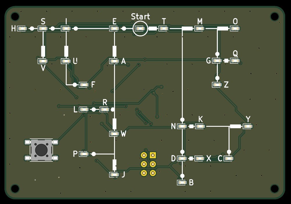
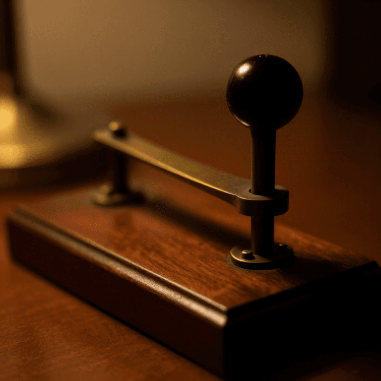
A pocket board, 80 x 55 mm, that teaches you to read Morse code. Its front is Dave Nathanson's Morse decoding chart: from Start, dots run one way and dashes the other, and every letter sits where its dots and dashes lead. Here every letter has its own LED. Press the key short for a dot and long for a dash, and the LED of the letter you have reached lights; pause, and it blinks. It runs on one CR2032 coin cell and sleeps between uses. The board was drawn with Youblob's Draw PCB, and its checks pass, but it has not been built yet.
پیشرفته
About 1 day, plus board delivery

دستورالعمل‌ها

1

LED current and keying speed

در حال بارگذاری دفترچهٔ Jupyter…
2

The code it decodes

This board reads the International Morse code letters as ITU-R M.1677-1 gives them.
3

Read the chart

Dave Nathanson (KG6ZJO) drew his decoding chart in 2010: "Start with your finger at "Start Here". Then move your finger to track the Morse dots & dashes. You will arrive at the correct letter!" On this board the LEDs do the tracking. ITU-R M.1677-1: "A dash is equal to three dots."
4

The schematic

ATmega328P on its internal 8 MHz clock, straight from the coin cell; 27 LEDs charlieplexed on PC0-PC5 through six 330 Ω resistors; the key on INT0; a 2x3 ISP footprint.

بارگذاری نمایشگر KiCanvas...

نمایشگر حرفه‌ای طراحی PCB

5

The board

Two layers, 80 x 55 mm. The chart, LEDs and key on the front; the chip, resistors, capacitors and cell holder on the back.

بارگذاری نمایشگر KiCanvas...

نمایشگر حرفه‌ای طراحی PCB

6

Order the board

Open the board in KiCad and plot Gerber and drill files (File > Fabrication Outputs). Order a two-layer board, 1.6 mm thick, from any board maker that takes Gerbers.

مواد مورد نیاز این مرحله:

برد مدار چاپیبرد مدار چاپی1 قطعه

ابزارهای مورد نیاز:
رایانه با Arduino IDEرایانه با Arduino IDE
7

Solder the parts

Back first: paste and reflow U1, R1-R7, C1-C3 and the cell holder BT1 with hot air. Then the front: the 27 red LEDs D1-D27 with pad 1 (cathode) as the board's assembly drawing shows, and the key SW1. Leave J1 empty. Clean off the flux, then test each LED's direction with the meter's diode test.

مواد مورد نیاز این مرحله:

میکروکنترلر ATmega328Pمیکروکنترلر ATmega328P1 قطعه
ال‌ای‌دی تراشه‌ایال‌ای‌دی تراشه‌ای27 قطعه
مقاومت تراشه‌ایمقاومت تراشه‌ای7 قطعه
خازن سرامیکی تراشه‌ایخازن سرامیکی تراشه‌ای3 قطعه
کلید فشاریکلید فشاری1 قطعه
نگهدارندهٔ باترینگهدارندهٔ باتری1 قطعه
خمیر لحیم (بدون سرب)خمیر لحیم (بدون سرب)1 قطعه
سیم لحیمسیم لحیم1 قطعه

ابزارهای مورد نیاز:

ایستگاه هویهٔ هوای گرمایستگاه هویهٔ هوای گرم
هویههویه
موچین نوک‌تیزموچین نوک‌تیز
فلاکس لحیمفلاکس لحیم
ذره‌بینذره‌بین
مولتی‌مترمولتی‌متر
ایزوپروپیل الکل ۹۹ ٪ایزوپروپیل الکل ۹۹ ٪
8

The firmware

pocket_morse_decoder_az.ino: every timing is a named constant at the top of the sketch. Board in the Arduino IDE: Arduino Pro or Pro Mini, ATmega328P (3.3V, 8 MHz).
pocket_morse_decoder_az.inoarduino
// Pocket Morse code decoder - ATmega328P-AU, internal 8 MHz, CR2032
// Board: Arduino Pro or Pro Mini, ATmega328P (3.3V, 8MHz) - burn fuses for internal RC (see notes)
// 27 LEDs charlieplexed on A0..A5 (PC0..PC5), button on D2 (INT0) to GND.
#include <avr/sleep.h>
#include <avr/power.h>
#include <avr/interrupt.h>

// ---------------- timing constants (ms) ----------------
const unsigned long DEBOUNCE_MS       = 20;     // button debounce
const unsigned long DASH_THRESHOLD_MS = 250;    // press shorter = dot, longer = dash
const unsigned long CHAR_GAP_MS       = 700;    // silence that ends a character
const unsigned long BLINK_ON_MS       = 150;    // result blink on time
const unsigned long BLINK_OFF_MS      = 150;    // result blink off time
const uint8_t       BLINK_COUNT       = 3;      // number of result blinks
const unsigned long IDLE_SLEEP_MS     = 30000;  // idle time before power-down

// ---------------- hardware ----------------
const uint8_t BUTTON_PIN = 2;                   // INT0, internal pull-up, active low
const uint8_t LINE_PINS[6] = {A0, A1, A2, A3, A4, A5};  // charlieplex lines CP1..CP6
const uint8_t MAX_CODE_LEN = 4;

struct Node {
  const char *code;   // "" = Start
  char label;
  uint8_t anode;      // index into LINE_PINS
  uint8_t cathode;
};

const Node NODES[] = {
  {"", ' ', 0, 2},   // D1
  {"-", 'T', 2, 0},   // D2
  {".", 'E', 1, 0},   // D3
  {"--", 'M', 2, 1},   // D4
  {"-.", 'N', 5, 1},   // D5
  {".-", 'A', 4, 1},   // D6
  {"..", 'I', 0, 1},   // D7
  {"---", 'O', 1, 2},   // D8
  {"--.", 'G', 2, 4},   // D9
  {"-.-", 'K', 1, 5},   // D10
  {"-..", 'D', 5, 3},   // D11
  {".--", 'W', 1, 4},   // D12
  {".-.", 'R', 3, 1},   // D13
  {"..-", 'U', 0, 4},   // D14
  {"...", 'S', 5, 0},   // D15
  {"--.-", 'Q', 5, 2},   // D16
  {"--..", 'Z', 4, 2},   // D17
  {"-.--", 'Y', 2, 5},   // D18
  {"-.-.", 'C', 5, 4},   // D19
  {"-..-", 'X', 4, 5},   // D20
  {"-...", 'B', 3, 5},   // D21
  {".---", 'J', 4, 3},   // D22
  {".--.", 'P', 3, 4},   // D23
  {".-..", 'L', 1, 3},   // D24
  {"..-.", 'F', 4, 0},   // D25
  {"...-", 'V', 0, 3},   // D26
  {"....", 'H', 3, 0},   // D27
};
const uint8_t NODE_COUNT = sizeof(NODES) / sizeof(NODES[0]);
const int8_t START_NODE = 0;

// ---------------- state ----------------
char seq[MAX_CODE_LEN + 2];
uint8_t seqLen = 0;
bool seqInvalid = false;
bool charPending = false;
bool btnStable = false;          // true = pressed
bool btnLastRaw = false;
unsigned long btnRawChange = 0;
unsigned long pressStart = 0;
unsigned long lastRelease = 0;
unsigned long lastActivity = 0;

void ledsOff() {
  for (uint8_t i = 0; i < 6; i++) {
    pinMode(LINE_PINS[i], INPUT);
    digitalWrite(LINE_PINS[i], LOW);
  }
}

void ledOn(int8_t idx) {
  ledsOff();
  if (idx < 0 || idx >= NODE_COUNT) return;
  uint8_t a = LINE_PINS[NODES[idx].anode];
  uint8_t c = LINE_PINS[NODES[idx].cathode];
  digitalWrite(c, LOW);
  pinMode(c, OUTPUT);
  digitalWrite(a, HIGH);
  pinMode(a, OUTPUT);
}

int8_t findNode(const char *code) {
  for (uint8_t i = 0; i < NODE_COUNT; i++) {
    if (strcmp(NODES[i].code, code) == 0) return i;
  }
  return -1;
}

void blinkNode(int8_t idx) {
  for (uint8_t k = 0; k < BLINK_COUNT; k++) {
    ledsOff();
    delay(BLINK_OFF_MS);
    ledOn(idx);
    delay(BLINK_ON_MS);
  }
  ledsOff();
  delay(BLINK_OFF_MS);
}

bool rawPressed() { return digitalRead(BUTTON_PIN) == LOW; }

// returns +1 on debounced press, -1 on debounced release, 0 otherwise
int8_t pollButton(unsigned long now) {
  bool raw = rawPressed();
  if (raw != btnLastRaw) { btnLastRaw = raw; btnRawChange = now; }
  if (raw != btnStable && (now - btnRawChange) >= DEBOUNCE_MS) {
    btnStable = raw;
    return raw ? 1 : -1;
  }
  return 0;
}

void resetSequence() {
  seqLen = 0;
  seq[0] = 0;
  seqInvalid = false;
  charPending = false;
}

ISR(INT0_vect) {
  EIMSK &= ~_BV(INT0);   // one-shot wake interrupt
}

void waitForRelease() {
  unsigned long t = millis();
  while (true) {
    if (rawPressed()) t = millis();
    if (millis() - t >= DEBOUNCE_MS) break;
  }
  btnStable = false; btnLastRaw = false;
}

void goToSleep() {
  ledsOff();
  set_sleep_mode(SLEEP_MODE_PWR_DOWN);
  cli();
  EICRA &= ~(_BV(ISC01) | _BV(ISC00));   // INT0 on low level (works in power-down)
  EIFR = _BV(INTF0);
  EIMSK |= _BV(INT0);
  sleep_enable();
  sleep_bod_disable();
  sei();
  sleep_cpu();
  sleep_disable();
  EIMSK &= ~_BV(INT0);
  // woken by the button: this press only wakes the board
  waitForRelease();
}

void wakeUp() {
  resetSequence();
  ledOn(START_NODE);
  lastActivity = millis();
}

void setup() {
  ADCSRA = 0;
  power_adc_disable();
  power_spi_disable();
  power_twi_disable();
  power_usart0_disable();
  power_timer1_disable();
  power_timer2_disable();
  ACSR = _BV(ACD);                 // analog comparator off
  DIDR0 = 0x3F;                    // digital input buffers off on PC0..PC5 (outputs only)
  for (uint8_t p = 0; p <= 13; p++) pinMode(p, INPUT_PULLUP);  // unused pins defined
  pinMode(BUTTON_PIN, INPUT_PULLUP);
  ledsOff();
  delay(5);
  btnLastRaw = btnStable = rawPressed();
  wakeUp();
}

void loop() {
  unsigned long now = millis();
  int8_t ev = pollButton(now);

  if (ev == 1) {                         // press
    pressStart = now;
    lastActivity = now;
  } else if (ev == -1) {                 // release: classify
    unsigned long dur = now - pressStart;
    char sym = (dur < DASH_THRESHOLD_MS) ? '.' : '-';
    if (seqLen < MAX_CODE_LEN) {
      seq[seqLen++] = sym;
      seq[seqLen] = 0;
    } else {
      seqInvalid = true;
    }
    int8_t idx = seqInvalid ? -1 : findNode(seq);
    if (idx < 0) { seqInvalid = true; ledsOff(); }
    else ledOn(idx);
    charPending = true;
    lastRelease = now;
    lastActivity = now;
  }

  if (charPending && !btnStable && (now - lastRelease) >= CHAR_GAP_MS) {
    int8_t idx = seqInvalid ? -1 : findNode(seq);
    if (idx >= 0) blinkNode(idx);
    else blinkNode(START_NODE);
    resetSequence();
    ledOn(START_NODE);
    lastActivity = millis();
  }

  if (!charPending && !btnStable && (millis() - lastActivity) >= IDLE_SLEEP_MS) {
    goToSleep();
    wakeUp();
  }
}
9

Set the fuses and upload

Do not use Burn Bootloader: the Pro board setting expects a crystal, and this board has none. Hold an ISP programmer's 2x3 pins on J1 and set the internal 8 MHz clock: avrdude -c usbasp -p m328p -U lfuse:w:0xE2:m -U hfuse:w:0xD9:m -U efuse:w:0xFF:m. Then, in the Arduino IDE, use Sketch > Upload Using Programmer.

ابزارهای مورد نیاز:

پروگرامر AVR ISPپروگرامر AVR ISP
رایانه با Arduino IDEرایانه با Arduino IDE
10

Print the back shell

An open-front shell, 84.8 x 59.8 x 8.9 mm, with four standoffs for M2 screws, a slot to slide the cell out and a window under J1. PLA, 0.2 mm layers, 20 % infill, printed on its floor.
فایل طراحیSTLCC0 - Free
11

Fit the shell

The shell leaves 5.0 mm for the back parts: measure your cell holder with a cell in it before you print. Check the holder's open side faces the board's left edge, where the shell's cell slot is. Slide in a CR2032 and screw the board into the shell with four M2 self-tapping screws.

مواد مورد نیاز این مرحله:
فیلامنت PLAفیلامنت PLA1 قطعه
پیچ خودکارپیچ خودکار4 قطعه
باتری سکه‌ای CR2032باتری سکه‌ای CR20321 قطعه

ابزارهای مورد نیاز:

چاپگر سه‌بعدی رشته‌ای (FDM)چاپگر سه‌بعدی رشته‌ای (FDM)
کولیس ورنیهکولیس ورنیه
مجموعهٔ پیچ‌گوشتی دقیقمجموعهٔ پیچ‌گوشتی دقیق
12

Troubleshooting

Pocket Morse decoder troubleshooting.

Flow

Loading...
13

History and honest limits

The chart is **Dave Nathanson**'s (KG6ZJO), drawn in 2010 and shared as copyleft; his post says it is a novel way to decode by following a path. The letter codes are ITU-R M.1677-1's. The board, sizes, parts and timings are ours, drawn with Youblob's Draw PCB: its ERC and DRC pass with no errors and every LED's wiring was checked against the firmware by script, but it has not been built, flashed or tested.

مواد

12

ابزارهای لازم

12

فایل‌های طراحی

1

این نقشه می‌سازد

CC0 مالکیت عمومی

این نقشه تحت مجوز CC0 منتشر شده است. شما آزاد هستید آن را کپی، ویرایش، توزیع و برای هر هدفی بدون نیاز به اجازه استفاده کنید.

با خرید محصولات از طریق نقشه از سازنده حمایت کنید و او کمیسیون سازنده تعیین شده توسط فروشندگان، دریافت می‌کند یا یک نسخه جدید از این نقشه ایجاد کنید و آن را به عنوان اتصال در نقشه خود قرار دهید تا درآمد به اشتراک گذاشته شود.

بحث و گفتگو

(0)

ورود برای شرکت در بحث

در حال بارگذاری نظرات...