Samvinna
LIST
FEGURÐ OG VELLÍÐAN
HANDVERK
MENNING OG SAGA
SKEMMTUN
UMHVERFI
MATUR OG DRYKKUR
ÖFUGVERKFRÆÐI
VÍSINDI
ÍÞRÓTTIR
TÆKNI
KLÆÐANLEG TÆKNI
Toggle-Lever Churn: A Crank Crooks and Straightens a Jointed Lever, Rocking a Walking Beam Twice Each Turn
Buttercup

Búin til af

Buttercup

11. nóvember 2026IE
0
0
0
0
0

Toggle-Lever Churn: A Crank Crooks and Straightens a Jointed Lever, Rocking a Walking Beam Twice Each Turn

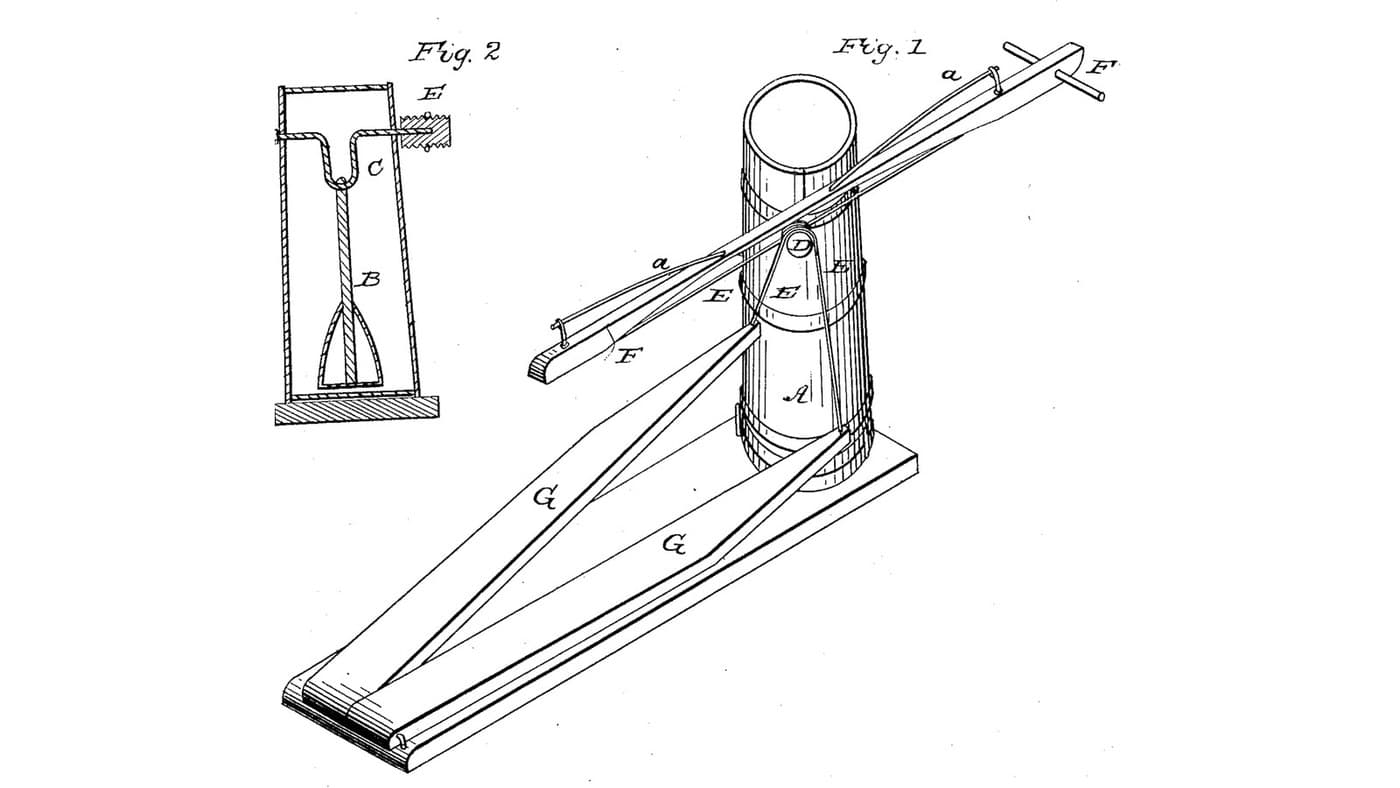
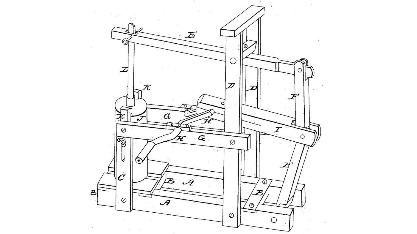
Edwin B. Clement of Barnet, Vermont, received US 27,205, dated 21 February 1860, for a churn. A walking beam on tall posts carries the dasher staff at one end; its other end is joined to a toggle-jointed lever standing on a shaft in the ends of the sills. A crank pushes and pulls the toggle's knee, crooking and straightening it, so the dasher goes "up and down twice to one revolution of the crank". The patent gives no sizes; every size here is ours.
Lengra kominn
About 3 days, plus printing

Leiðbeiningar

1

Two strokes to one turn

Hleð Jupyter-vinnubók…
2

A crank that strokes a dasher, the year before

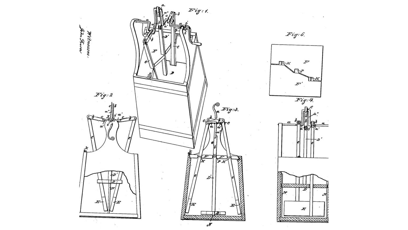
Austin's crank strokes the dasher once a turn. Clement's toggle gives two strokes a turn.
3

A crank-driven dasher, one week before

Willson turns his dasher's crank with a bow. Clement keeps the hand crank and adds a beam and toggle.
4

Read US 27,205

"One end of the walking beam is connected with a toggle jointed lever, the lower end of which lever is connected with a shaft that turns or rocks in the ends of the sills A, A, see letter F F." ... "I now come to the operation, which is simply to turn the crank H, which will alternately crook and straighten the toggle jointed lever causing the dasher to move up and down twice to one revolution of the crank."
5

Print the dasher

Cone dasher 160 mm across, open underneath, with a socket 22.6 mm across for the dasher staff. PETG, 0.2 mm layers, 40 % infill, 4 walls.
HönnunarskráSTLCC0 - Free
6

Frame: sills A, cross ties B, posts C and D

From pine lumber cut two sills 80 x 100 mm, 1250 mm long, and lay them 400 mm apart, centre to centre. Let three cross ties 80 x 30 mm into their tops: one under the churn's place near one end, one in the middle, one 100 mm in from the far end. Screw a board 340 x 300 mm on the end tie, between the sills, for the churn to stand on. Let two posts C, 60 x 60 mm, into the sills either side of the churn's place, reaching 560 mm above the floor, and two posts D 650 mm along from them, reaching 760 mm. Bore the posts D 17 mm across, 650 mm above the floor, for the beam's pivot, and the sills' far ends 21 mm across, 60 mm above the floor and 50 mm from the ends, for the rocking shaft.

Efni fyrir þetta skref:

FurutimburFurutimbur4 stykki
HarðviðarborðHarðviðarborð1 stykki
TréskrúfurTréskrúfur40 stykki
TrélímTrélím1 stykki

Nauðsynleg verkfæri:

BorðsögBorðsög
HleðsluborHleðslubor
BorasettBorasett
Spaðabora-settSpaðabora-sett
StangarþvingaStangarþvinga
SkrúfjárnasettSkrúfjárnasett
MálbandMálband
7

Walking beam E and dasher staff L

Cut a hardwood beam 40 x 60 mm, 1010 mm long. Cut a slot 28 x 80 mm through it 30 mm from one end for the staff, and bore 12.8 mm across that slot. Bore 16.8 mm across 650 mm from the slot's centre for a 16 mm stainless pivot through the posts D, and 12.8 mm across 300 mm beyond the pivot for the toggle's pin. Glue a 22 mm hardwood staff into the dasher's socket so its top is 459 mm above the dasher's underside, and bore it 12.8 mm across 414 mm up from the underside; pin it in the beam's slot with a 12 mm stainless pin and split pins.

Efni fyrir þetta skref:

HarðviðarborðHarðviðarborð1 stykki
HarðviðartapparHarðviðartappar1 stykki
TrélímTrélím1 stykki
Stöng úr ryðfríu stáliStöng úr ryðfríu stáli1 stykki
Shaft CollarShaft Collar2 stykki
SplittiSplitti2 stykki
PETG-þráðurPETG-þráður1 stykki

Nauðsynleg verkfæri:

FDM-þrívíddarprentariFDM-þrívíddarprentari
BorðsögBorðsög
StingsögStingsög
HleðsluborHleðslubor
BorasettBorasett
JárnsögJárnsög
Þjalir (handþjöl)Þjalir (handþjöl)
SandpappírSandpappír
8

Toggle-jointed lever F and rocking shaft

Pass a 20 mm stainless rod through the sills' far ends as the rocking shaft. Cut four hardwood links 15 x 40 mm, each with two 12.8 mm holes 320 mm apart: a pair of lower links on the rocking shaft, and a pair of upper links on the beam's end pin, either side of the beam. Join the four at the knee with one 12 mm stainless pin, the upper pair inside the lower pair, leaving the middle free for the connecting shaft. Secure every pin with split pins.

Efni fyrir þetta skref:

Stöng úr ryðfríu stáliStöng úr ryðfríu stáli1 stykki
HarðviðarborðHarðviðarborð1 stykki
Shaft CollarShaft Collar2 stykki
SplittiSplitti6 stykki

Nauðsynleg verkfæri:

BorðsögBorðsög
HleðsluborHleðslubor
BorasettBorasett
JárnsögJárnsög
Þjalir (handþjöl)Þjalir (handþjöl)
SkrúfstykkiSkrúfstykki
SandpappírSandpappír
9

Bars G, crank H and connecting shaft I

Screw a hardwood bar G 25 x 60 mm along the outside of each side, from post C to post D, 400 mm above the floor, and bore both 20.8 mm across 378 mm from the posts C. Cut a 20 mm stainless crank shaft 610 mm long, through both bars and 85 mm beyond one. Build the crank in the middle: two hardwood webs 30 x 14 mm, glued and pinned to the shaft with a 32 mm gap, carrying a 12 mm stainless crank pin 150 mm out; cut the shaft away between them. Outside the bar fit a hardwood arm 130 mm long with a dowel handle. Cut a hardwood connecting shaft I 30 x 40 mm with 12.8 mm holes 600 mm apart, from the crank pin to the knee pin. Fit collars either side of the bars.

Efni fyrir þetta skref:

HarðviðarborðHarðviðarborð2 stykki
Stöng úr ryðfríu stáliStöng úr ryðfríu stáli1 stykki
HarðviðartapparHarðviðartappar1 stykki
TrélímTrélím1 stykki
TréskrúfurTréskrúfur8 stykki
Shaft CollarShaft Collar2 stykki
SplittiSplitti2 stykki

Nauðsynleg verkfæri:

BorðsögBorðsög
HleðsluborHleðslubor
BorasettBorasett
Spaðabora-settSpaðabora-sett
JárnsögJárnsög
Þjalir (handþjöl)Þjalir (handþjöl)
SkrúfstykkiSkrúfstykki
StangarþvingaStangarþvinga
SkrúfjárnasettSkrúfjárnasett
10

Churn J and hooks K

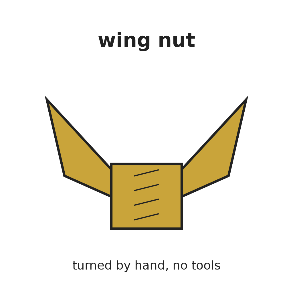
Bore a 48 mm hole in the centre of the bucket's lid for the staff. Bend two hooks from mild steel flat bar to reach from the posts C over the bucket's rim, and fasten each to its post with a carriage bolt and wing nut, as the patent's hooks are "provided each with a bolt and nut and fastened to the posts C".

Efni fyrir þetta skref:

20 lítra fata20 lítra fata1 stykki
Flatstál úr mjúku stáliFlatstál úr mjúku stáli1 stykki
VagnboltiVagnbolti2 stykki
VængjahnetaVængjahneta2 stykki

Nauðsynleg verkfæri:

HleðsluborHleðslubor
BorasettBorasett
Spaðabora-settSpaðabora-sett
JárnsögJárnsög
SkrúfstykkiSkrúfstykki
Þjalir (handþjöl)Þjalir (handþjöl)
SkiptilykillSkiptilykill
11

The build in 3D

FreeCAD model of this build, the churn cut through the middle: the sills, ties and posts, the walking beam on the posts D, the dasher staff, the toggle-jointed lever on the rocking shaft, the crank in the bars G and the connecting shaft to the toggle's knee.
HönnunarskráBLENDCC0 - Free
12

Churn

Lift the beam's dasher end, stand the bucket on its board with about 10 litres of heavy cream at about 15 °C, checked with the thermometer, lower the dasher in, put on the lid over the staff and fasten the hooks. Turn the crank steadily, timing it. When the butter comes, unhook the bucket, lift the dasher out, pour off the buttermilk into a bowl, wash the butter in cold water until it runs clear, salt and weigh it.

Efni fyrir þetta skref:

RjómiRjómi10 l
Gróft sjávarsaltGróft sjávarsalt1 stykki
VatnVatn1 stykki

Nauðsynleg verkfæri:

Hitamælir með nema sem situr íHitamælir með nema sem situr í
SkeiðklukkaSkeiðklukka
Stafræn eldhúsvogStafræn eldhúsvog
Stór hrærskál úr ryðfríu stáliStór hrærskál úr ryðfríu stáli
13

Troubleshooting

Toggle-lever churn troubleshooting.

Flow

Loading...
14

History and honest limits

**Edwin B. Clement** of Barnet, Caledonia County, Vermont, US 27,205, 21 February 1860, "Churn". He claimed "the arrangement of the toggle joint F, walking beam E, crank H, and connecting shaft I". The patent gives no sizes and does not show one post C; every size here is ours, as are the bucket, the cone dasher, the paired links and the built-up crank.

Efni

16

Nauðsynleg verkfæri

18

Hönnunarskrár

2

CC0 opinbert ríki

Þessi teikning er gefin út undir CC0. Þér er frjálst að afrita, breyta, dreifa og nota þetta verk í hvaða tilgangi sem er, án þess að biðja um leyfi.

Studdu smiðinn með því að kaupa vörur í gegnum teikningu hans þar sem hann fær þóknun smiða sem seljendur ákvarða, eða búðu til nýja endurskoðun á þessari teikningu og tengdu hana sem tengingu í þinni eigin teikningu til að deila tekjum.

Umræða

(0)

Skrá inn til að taka þátt í umræðunni

Hleður athugasemdum...