Samvinna
LIST
FEGURÐ OG VELLÍÐAN
HANDVERK
MENNING OG SAGA
SKEMMTUN
UMHVERFI
MATUR OG DRYKKUR
ÖFUGVERKFRÆÐI
VÍSINDI
ÍÞRÓTTIR
TÆKNI
KLÆÐANLEG TÆKNI
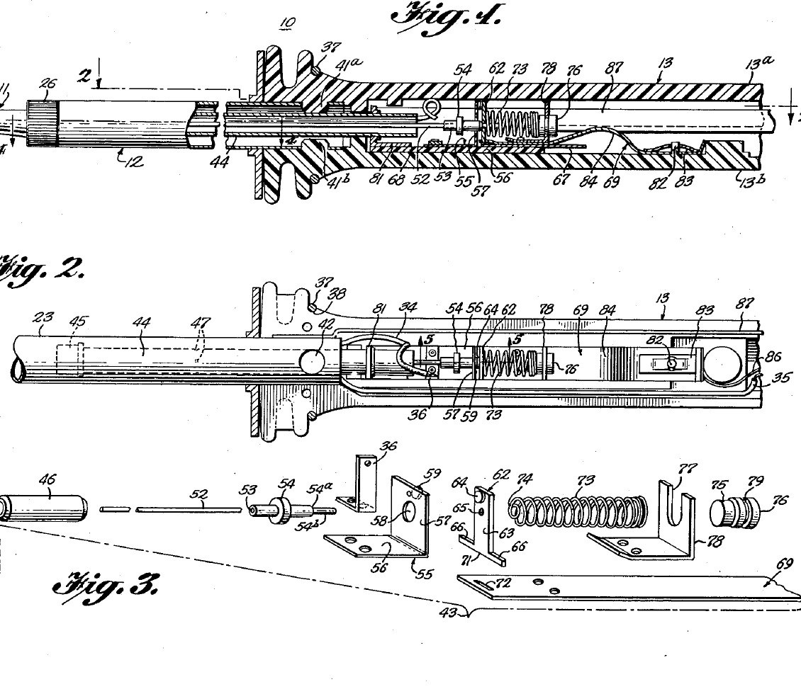


Soldering Iron: Temperature Controlled by a Curie-Point Tip and a Magnet Switch (Weller, US 3,188,448, 1965)
A soldering iron that holds its own tip temperature. At the back of the copper tip sits a slug of nickel-iron alloy that stops being magnetic above a set temperature (its Curie point). A small Alnico magnet behind it is pulled forward while the slug is cool, closing a switch that feeds the heater; once the tip is hot the slug lets go, a steel bushing pulls the magnet back and the switch opens. Swap tips to choose 600, 700 or 800 °F.
Result: a 55-watt temperature-controlled iron idling near 700 °F instead of running ever hotter.
Source: C. E. Weller, US 3,188,448 (1965). Unknown: the plating baths, the heater wire and insulation, most sizes. Picture: the patent drawing.
Lengra kominn
Unknown
Leiðbeiningar
1
1
Make the tip and control slug
Make the tip and control slug
Turn the tip from tellurium copper: a cylindrical body, a taper and a chisel end (any shape suits the work). Plate it first with iron, which keeps the copper out of the molten solder, then with nickel, which shuts out the air. Bore its rear end and fit tightly into it the shank of a slug of thermomagnetic nickel-iron alloy, such as 48 % nickel, 3 % molybdenum and the rest iron, or about 43 % nickel and the rest iron. The alloy sets the control point: make tips for 600, 700 and 800 °F. Not given: the plating baths, sizes.
Efni fyrir þetta skref:
 Tellúrkoparstöng1 tip
 Hitasegulmagnað nikkel-járnmelmi1 control slug
Nauðsynleg verkfæri:
 Málmrennibekkur
 Rafhúðunarsett
 Óþekkt mál
2
2
Wind the heater barrel
Wind the heater barrel
Make the barrel of two stainless steel tubes: an inner spool the tip slides into snugly, and an outer cover tube joined to it at the front, with a thread and screw cap to hold the tip. In the space between them wind the heater from one length of resistance wire: an inner layer, then an outer layer wound the opposite way so their fields cancel, with insulating sheet inside, between and outside the layers. Silver-solder heat-resistant leads to its ends. Ours: nichrome wire. Not given: the insulating sheet, the turns.
Efni fyrir þetta skref:
 Rör úr ryðfríu stáli2 spool and cover tube
 Nikrómvír1 heater
 Óþekkt einangrunarefni1 three sheet layers
 Óþekktur málmur1 leads
 Silfurlóð1 as needed
Nauðsynleg verkfæri:
 PrópanbrennariMálmrennibekkur
3
3
Build the magnet switch
Build the magnet switch
In a stainless steel sleeve about 2.4 in long, close the front with a non-magnetic thermal bushing. Behind it slides a cylindrical Alnico V magnet, then a non-magnetic spacer about 0.032 in thick, then a cold-drawn steel bushing about 0.50 in long held by dents in the sleeve; the magnet's stroke is about 0.015 in. A push rod runs from the magnet through the bushing to an insulator. On a melamine plate, hinge a moving contact between a thin conducting strip and a holding strip, facing a flexible contact; a spring of fourteen coils of 0.010 in music wire, 0.210 in across, presses the moving contact toward the flexible one. Rivet the spring bracket to the holding strip. Not given: the contact metals.
Efni fyrir þetta skref:
Rör úr ryðfríu stáli1 sleeve Alnico-segull1 stykki
 Kringlótt stöng úr deigu stáli1 magnetic bushing, push rodÓþekktur málmur1 thermal bushing, spacer, contacts, strips, brackets
 Óþekktur efniviður1 insulator
 Melamínplata1 base plate
 Fjaðurstálsvír1 0.010 in music wire spring
Nauðsynleg verkfæri:
Málmrennibekkur Hnoðsett
 Kringlunefjatöng
4
4
Assemble the handle and use
Assemble the handle and use
Mould the handle in two plastic halves with a socket at the front whose bosses lock the cover tube. Lay in the switch unit, held only by the bowed tail of its holding strip on an anchor pin with a speed nut, so it floats and its thermal bushing presses on the tip's slug. Wire the heater, the switch and a ground lead from the cover tube to the cord. Rivet the halves near the butt and fit a split ring near the front. In use, below the control point the slug pulls the magnet forward and the spring closes the contacts; above it the steel bushing pulls the magnet back and the push rod opens them. At idle the heater runs only about 30 to 40 % of the time. Not given: the plastic.
Efni fyrir þetta skref:
Óþekktur efniviður1 handle halvesÓþekktur málmur1 rivet, split ring, speed nut Sveigjanleg snúra með kló1 stykki
Nauðsynleg verkfæri:
 SprautusteypuvélHnoðsett
Efni
13- 1 tipStaðgengill
- 1 control slugStaðgengill
- 1 sleeveStaðgengill
- 1 heaterStaðgengill
- 1 three sheet layersStaðgengill
- 1 rivet, split ring, speed nutStaðgengill
- 1 as neededStaðgengill
- 1 stykkiStaðgengill
- 1 magnetic bushing, push rodStaðgengill
- 1 handle halvesStaðgengill
- 1 base plateStaðgengill
- 1 0.010 in music wire springStaðgengill
- 1 stykkiStaðgengill
Nauðsynleg verkfæri
7- Staðgengill
- Staðgengill
- Staðgengill
- Staðgengill
- Staðgengill
- Staðgengill
- Staðgengill
Efni úr tengdum teikningum

Þessi teikning býr til

CC0 opinbert ríki
Þessi teikning er gefin út undir CC0. Þér er frjálst að afrita, breyta, dreifa og nota þetta verk í hvaða tilgangi sem er, án þess að biðja um leyfi.
Studdu smiðinn með því að kaupa vörur í gegnum teikningu hans þar sem hann fær þóknun smiða sem seljendur ákvarða, eða búðu til nýja endurskoðun á þessari teikningu og tengdu hana sem tengingu í þinni eigin teikningu til að deila tekjum.