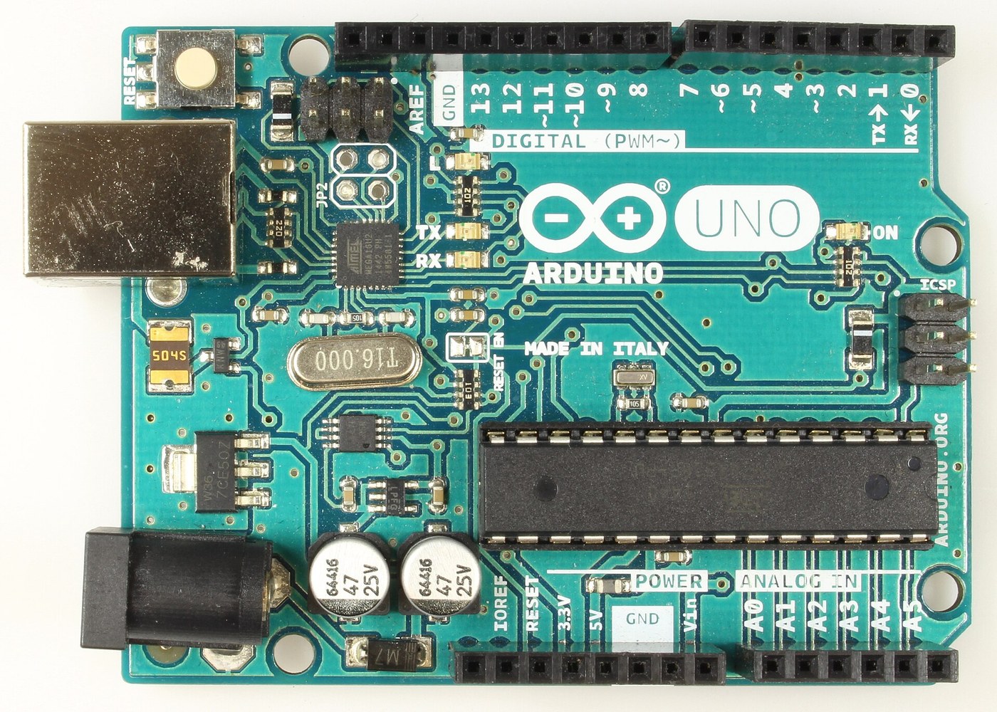


Arduino Uno R3: Assembled from Arduino's Open UNO-TH Rev3e Design Files and Flashed over ICSP
Istruzioni
Get the bare board
Get the bare board
Materiali per questo passaggio:
 Circuito stampato1 UNO-TH Rev3e layout
Strumenti necessari:
 Lente da orologiaio
Fit the small surface-mount parts
Fit the small surface-mount parts
Materiali per questo passaggio:
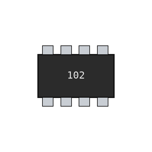 Rete di resistori chip4 RN1-RN4
 Resistore chip2 1M
 Condensatore ceramico chip11 7x100n, 2x1u, 2x22p
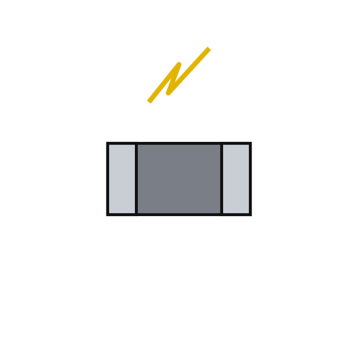 Varistore chip2 Z1, Z2
 Perla di ferrite1 L1
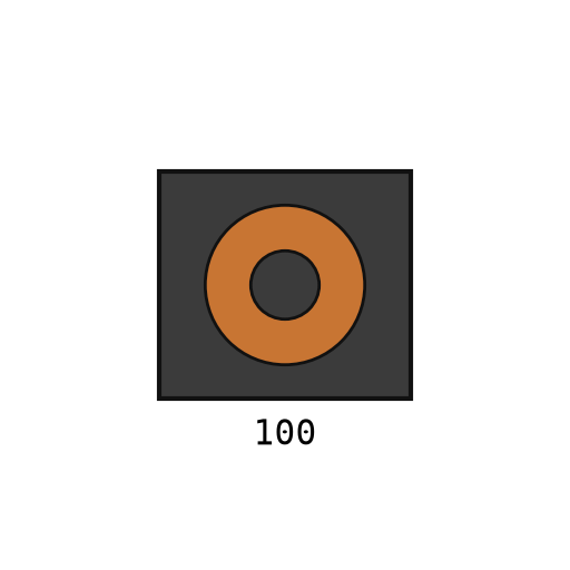 Induttore SMD1 L2
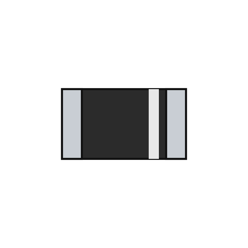 Diodo SMD2 D2, D3
 LED chip4 1 green, 3 yellow
 Filo per saldatura1 a little
Strumenti necessari:
 Flussante
 Pinzetta a punte fini
 Stazione di rilavorazione ad aria calda
 Saldatore a stagnoLente da orologiaio
Fit the power and chip parts
Fit the power and chip parts
Materiali per questo passaggio:
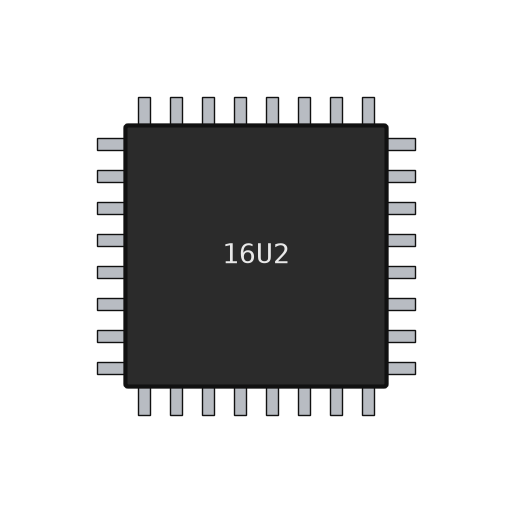 Microcontrollore ATmega16U21 U3
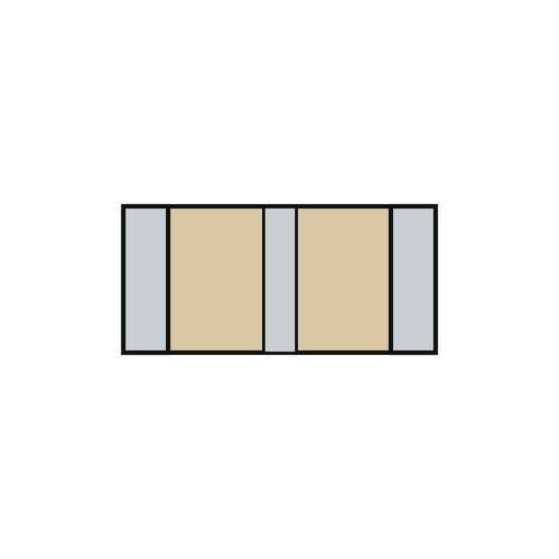 Risonatore ceramico piezoelettrico1 Y2
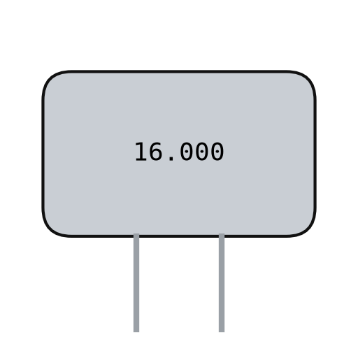 Cristallo di quarzo1 Y1
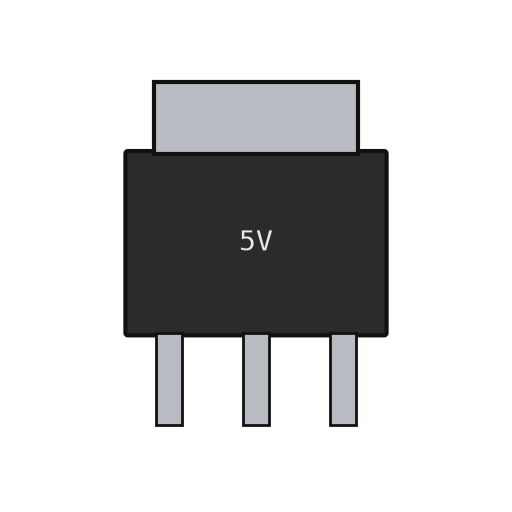 Regolatore di tensione lineare2 U1 5 V, U2 3.3 V
 Circuito integrato amplificatore operazionale1 U5 LMV358
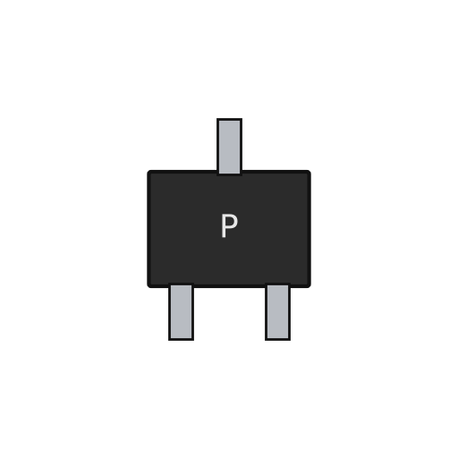 MOSFET a canale P1 T1Diodo SMD1 D1 M7
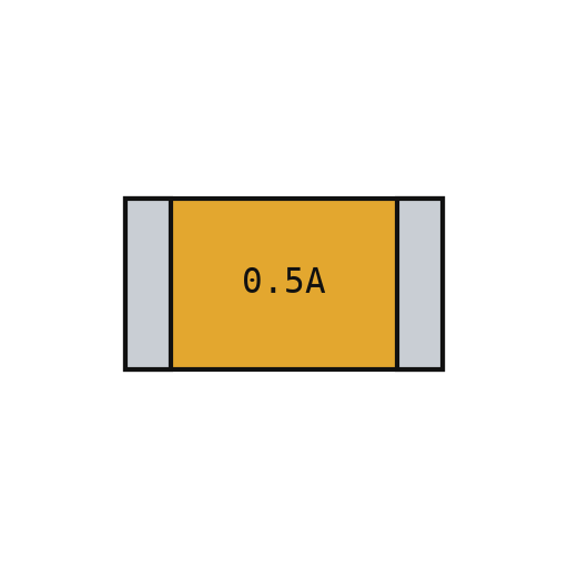 Fusibile ripristinabile1 F1
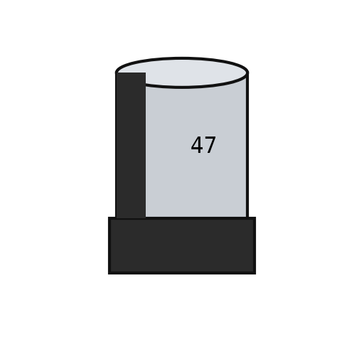 Condensatore chip polarizzato2 PC1, PC2Filo per saldatura1 a little
Strumenti necessari:
FlussantePinzetta a punte finiStazione di rilavorazione ad aria caldaSaldatore a stagnoLente da orologiaioFit the through-hole parts
Fit the through-hole parts
Materiali per questo passaggio:
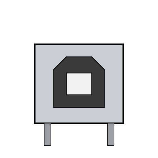 Presa USB-B1 X2
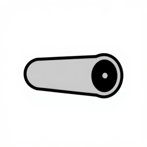 Presa di alimentazione1 X1
 Pulsante1 RESET
 Strip di contatti6 10x1, 2x 8x1, 6x1 female; 2x 3x2 ICSP
 Microcontrollore ATmega328P1 ZU4Filo per saldatura1 as needed
Strumenti necessari:
Saldatore a stagnoFlash and check
Flash and check
Materiali per questo passaggio:
 Firmware di Arduino Uno1 download
Strumenti necessari:
 Multimetro
 Programmatore AVR ISP
 Cavo USB-B
The blink test
The blink test
Strumenti necessari:
Cavo USB-BMateriali
24- 1 UNO-TH Rev3e layoutSegnaposto
- 4 RN1-RN4Segnaposto
- 2 1MSegnaposto
- 11 7x100n, 2x1u, 2x22pSegnaposto
- 2 Z1, Z2Segnaposto
- 1 L1Segnaposto
- 1 L2Segnaposto
- 1 D1 M7Segnaposto
- 4 1 green, 3 yellowSegnaposto
- 1 as neededSegnaposto
- Segnaposto
- Segnaposto
- Segnaposto
- 2 U1 5 V, U2 3.3 VSegnaposto
- Segnaposto
- Segnaposto
- Segnaposto
- 2 PC1, PC2Segnaposto
- 1 X2Segnaposto
- Segnaposto
- Segnaposto
- Segnaposto
- Segnaposto
- 1 downloadSegnaposto
Strumenti richiesti
8- Segnaposto
- Segnaposto
- Segnaposto
- Segnaposto
- 2 vendors sell this, none ship to you yetSegnaposto
- Segnaposto
- Segnaposto
- 1 vendor sell this, none ship to you yetSegnaposto
Questo progetto realizza
Blueprint correlati
Questi blueprint condividono conoscenze — tecniche, materiali o principi
CC0 Pubblico dominio
Questo progetto è rilasciato sotto CC0. Sei libero di copiare, modificare, distribuire e utilizzare quest'opera per qualsiasi scopo, senza chiedere permesso.
Supporta il Maker acquistando prodotti tramite il suo progetto dove guadagna una Commissione Maker stabilita dai venditori, oppure crea una nuova iterazione di questo progetto e includilo come collegamento nel tuo progetto per condividere i ricavi.