Collaborazione
ARTE
BELLEZZA E BENESSERE
MESTIERE
CULTURA E STORIA
DIVERTIMENTO
AMBIENTE
CIBO E BEVANDE
INGEGNERIA INVERSA
SCIENZE
SPORT
TECNOLOGIA
INDOSSABILI
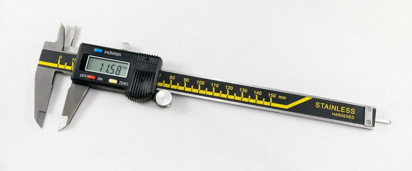


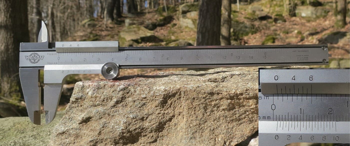
Digital Caliper: Capacitive Scale and Slider with Two-Chip Electronics (Baxter and Buehler, Starrett, 1986)
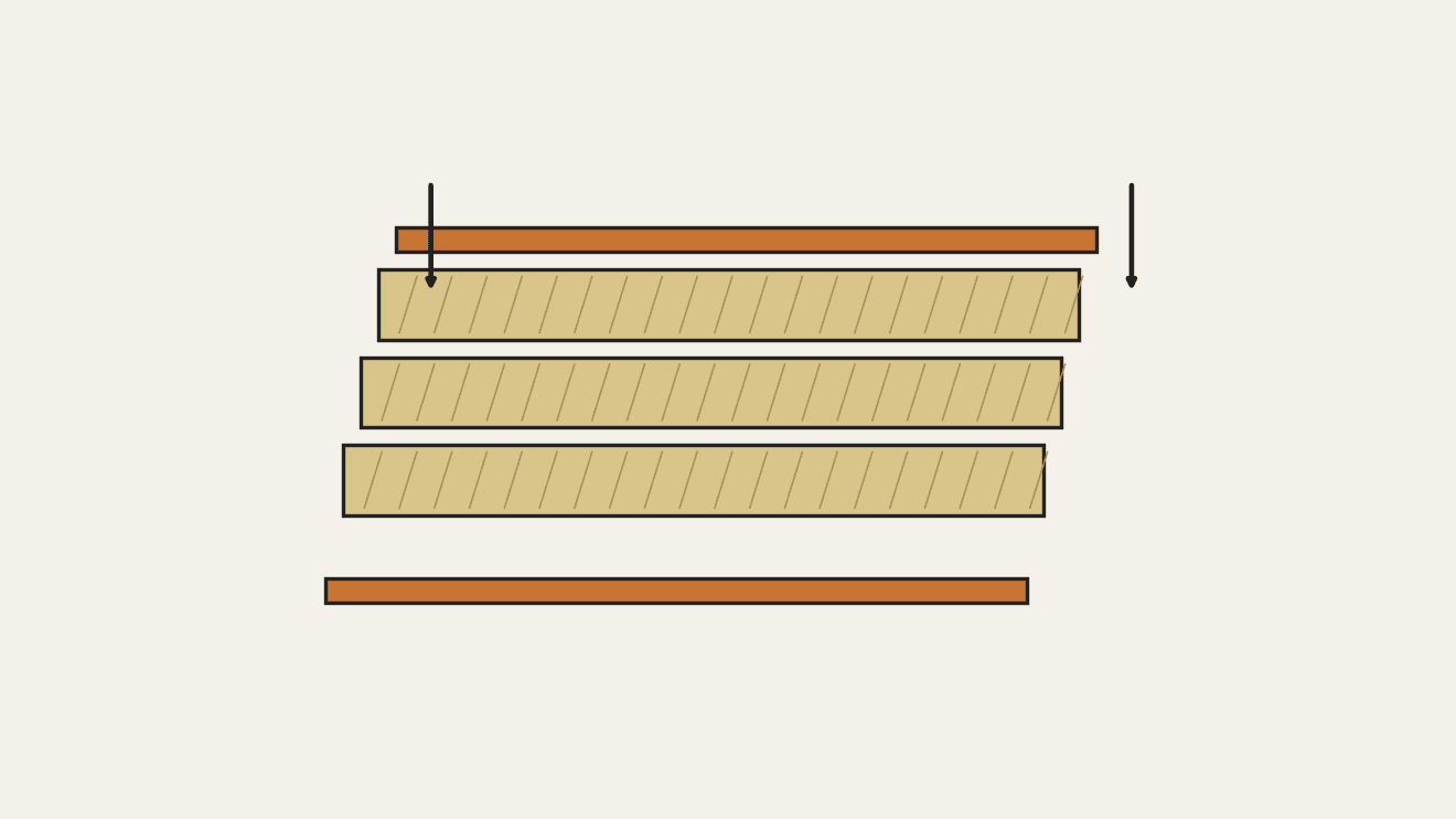
A six-inch caliper that reads out on a display. Under the slide, a strip of etched copper bars runs along the beam. Electrodes on the slider pass a signal through the bars by capacitance, and the slider's electronics count the bars crossed and work out the position in between.
Result: a digital caliper reading in inches or millimetres, repeatable to a ten-thousandth of an inch, with floating zero, peak hold and high/low limits. It runs on two 1.5 V cells at 10-50 microamps.
Source: L. K. Baxter and R. J. Buehler (L. S. Starrett Co.), US Patent 4,586,260 (1986). Unknown: the metal of the beam, slide and rod, their dimensions, the processor's program, and how the chips and display are made. Ours: the etchant, photoresist and glue. Picture: Wikimedia Commons.
Avanzato
2 days
Istruzioni
1
1
Etch the scale
Etch the scale
Etch the scale pattern onto a strip of copper-clad epoxy fibreglass with photoresist and etchant. Each copper bar is 0.40 inch long, with a wider centre 0.12 inch long and two ends 0.14 inch long. Space the bars on 0.05 inch centres: the centres sit 0.004 inch apart, the ends 0.025 inch apart. Run the pattern the full length of the scale. Ours: dry film resist and ferric chloride.
Materiali per questo passaggio:
 Basetta vergine per circuito stampato (ramata)1 strip, length of the beam
Strumenti necessari:
 Fotoresist a film secco
 Soluzione di cloruro ferrico
 Guanti resistenti agli agenti chimici
2
2
Fix the scale into the beam
Fix the scale into the beam
The beam is a metal bar with the fixed outside and inside jaws at one end, a wide shallow channel in its face and a second channel along its back. Fix the scale permanently into the face channel, copper up. The patent allows etching before or after this step. Not given: the metal, the dimensions and how the scale is fixed. Ours: epoxy.
Materiali per questo passaggio:
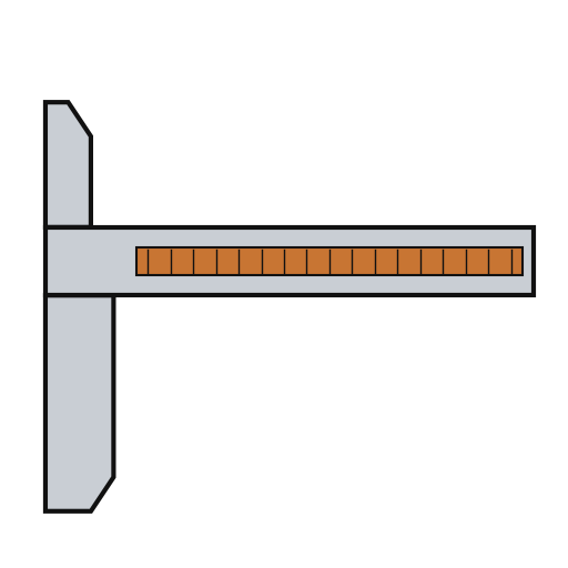 Asta del calibro1 with integral jaws
 Resina epossidica bicomponente1 a little
Strumenti necessari:
 Dimensioni sconosciute
3
3
Fit the parts to the circuit
Fit the parts to the circuit
The circuit is one folded piece: a double-sided slider board joined by a flexible hinge to a circuit board. Its bottom face has two pickup electrodes, 0.750 x 0.110 inch and 0.0625 inch apart. On each side of them is an interdigitated transmitter array: fingers 0.115 inch long on 0.025 inch spacing, opening to 0.0375 inch at the centre. On the circuit board, solder or wire-bond the two chips: an NEC uPD7503 3 V processor (768 bits RAM, 2 kB ROM) and a CMOS gate array. Then fit the LCD, the 100 kHz crystal, the integrating capacitor and the MODE and SET buttons. Not given: the processor's program. Ours: a capacitor from a kit.
Materiali per questo passaggio:
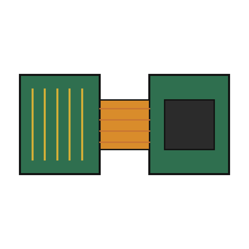 Circuito stampato rigido-flessibile1 slider board + circuit board
 Circuito integrato2 uPD7503 CPU, CMOS gate array
 Display LCD a segmenti1 5 digits
 Cristallo di quarzo1 100 kHz
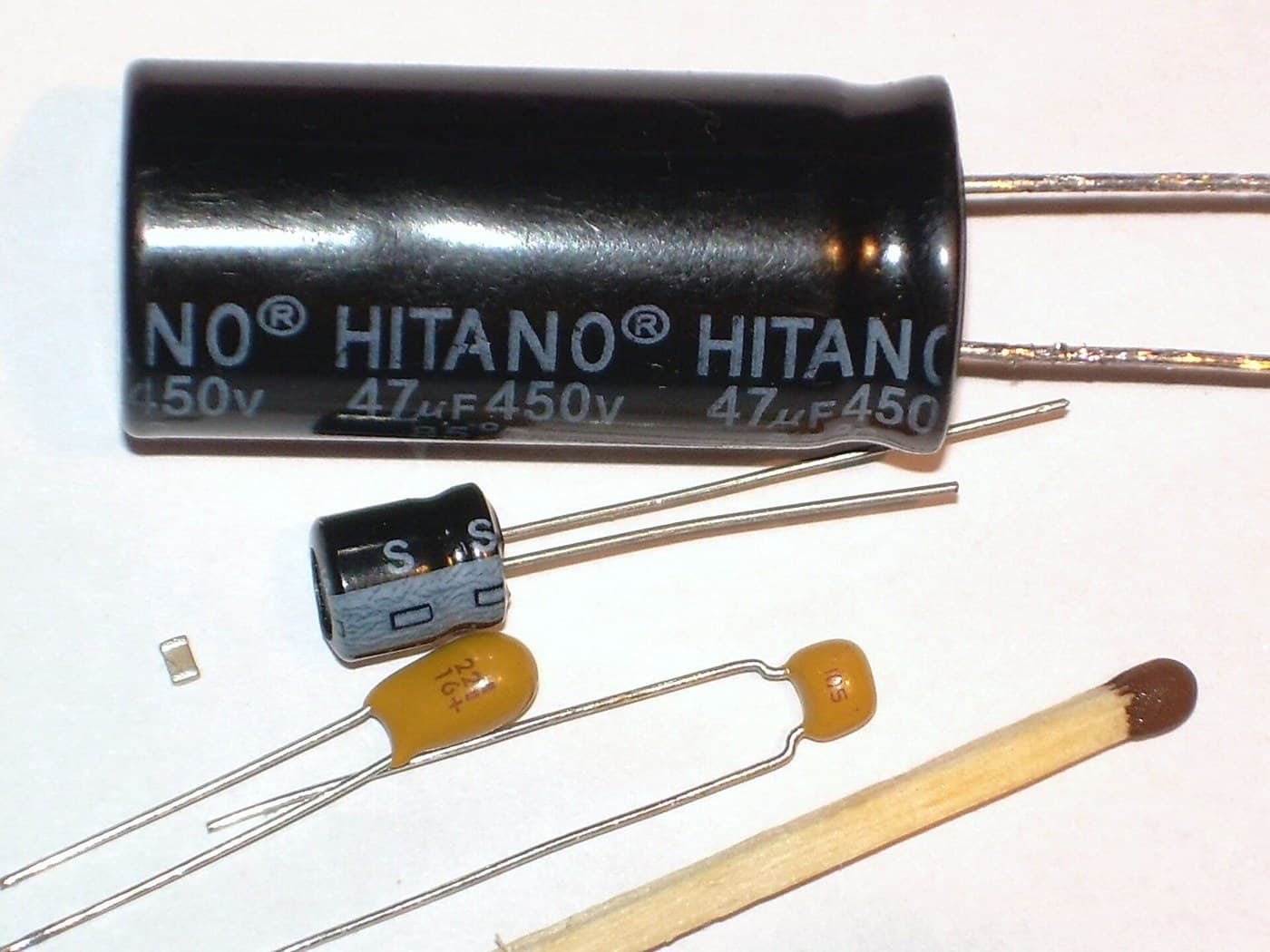
 Kit di condensatori1 one integrating capacitor
 Pulsante2 MODE, SET
 Filo per saldatura1 a little
Strumenti necessari:
 Saldatore a stagno
4
4
Build the slide
Build the slide
The slide frame wraps the back and edges of the beam and carries the movable jaws. Fix it to the depth rod, which runs in the back channel of the beam; the rod's free end is the depth gauge. Put the moulded plastic housing between the frame ends. Fasten two metal wear strips under the slider board, one on each side of the scale. They ride on the beam and connect the board's copper to it. Not given: the metal and sizes.
Materiali per questo passaggio:
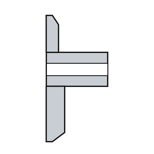 Telaio del cursore1 with jaws
 Metallo sconosciuto1 depth rod and two wear strips
 Custodia del cursore1 pezzo
Strumenti necessari:
Dimensioni sconosciute Set di cacciaviti di precisione
5
5
Assemble and check
Assemble and check
Fold the circuit into the housing recess, slider board facing the scale, and screw it to the frame. The electrodes must lie parallel to the scale bars at every point of travel. Put the two 1.5 V cells (the patent says 'zinc oxide') in the battery pockets of the circuit. The display shows five digits, a ten-thousandths bar graph, a minus sign and 'mm', plus PEAK, LOW, HIGH and LIMIT. Ours: check the reading against a vernier caliper.
Materiali per questo passaggio:
 Viti da metallo2 pezzi
 Pila a bottone da 1,5 V2 pezzi
Strumenti necessari:
Set di cacciaviti di precisione Calibro a corsoio
Materiali
15- 1 strip, length of the beamSegnaposto
- 1 with integral jawsSegnaposto
- 1 a littleSegnaposto
- 1 slider board + circuit boardSegnaposto
- 2 uPD7503 CPU, CMOS gate arraySegnaposto
- 1 5 digitsSegnaposto
- 1 100 kHzSegnaposto
- 1 one integrating capacitorSegnaposto
- Segnaposto
- 1 a littleSegnaposto
- 1 with jawsSegnaposto
- 1 depth rod and two wear stripsSegnaposto
- 1 pezzoSegnaposto
- 2 pezziSegnaposto
- 2 pezziSegnaposto
Strumenti richiesti
7- Segnaposto
- Segnaposto
- Segnaposto
- Segnaposto
- 2 vendors sell this, none ship to you yetSegnaposto
- Segnaposto
- Segnaposto
Materiali dei progetti collegati

Questo progetto realizza

Blueprint correlati
Questi blueprint condividono conoscenze — tecniche, materiali o principi
CC0 Pubblico dominio
Questo progetto è rilasciato sotto CC0. Sei libero di copiare, modificare, distribuire e utilizzare quest'opera per qualsiasi scopo, senza chiedere permesso.
Supporta il Maker acquistando prodotti tramite il suo progetto dove guadagna una Commissione Maker stabilita dai venditori, oppure crea una nuova iterazione di questo progetto e includilo come collegamento nel tuo progetto per condividere i ricavi.