Collaborazione
ARTE
BELLEZZA E BENESSERE
MESTIERE
CULTURA E STORIA
DIVERTIMENTO
AMBIENTE
CIBO E BEVANDE
INGEGNERIA INVERSA
SCIENZE
SPORT
TECNOLOGIA
INDOSSABILI
Shifting-Gear Grinding-Disk Churn: One Crank Wheel Is Thrown Into Gear With the Wings Below, the Grinding Disk Above, or Both
Buttercup

Creato da

Buttercup

12. novembre 2026IE
0
0
0
0
0

Shifting-Gear Grinding-Disk Churn: One Crank Wheel Is Thrown Into Gear With the Wings Below, the Grinding Disk Above, or Both

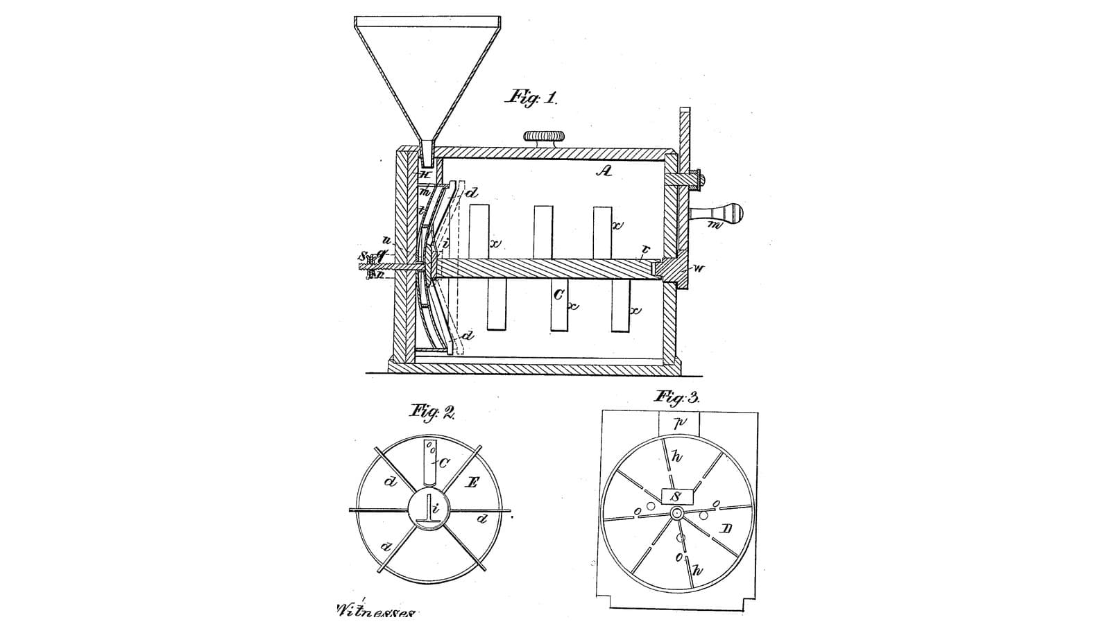
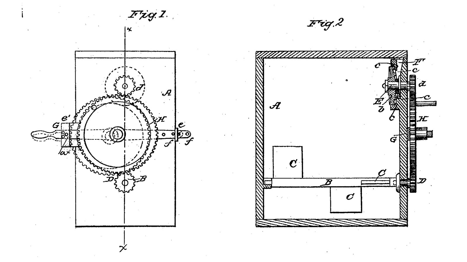
John Fowler and W. L. Walter of Homer, New York, received US 32,939, dated 30 July 1861, for a box churn with two working parts on one crank. High in the box a turning disk grinds the cream poured from a hopper against a fixed ribbed disk, and the cream falls below, out of their way; low in the box a shaft of wings gathers the butter. The crank wheel rides on a bar that slides and tilts in two guides on the box's side, so it can be put in gear with the disk alone, the wings alone, or both, and pinned there. The patent gives no sizes; every size here is ours.
Avanzato
About 3 days

Istruzioni

1

One wheel, two pinions

Caricamento del notebook Jupyter…
2

Cream ground once between disks as it is poured in, three months before

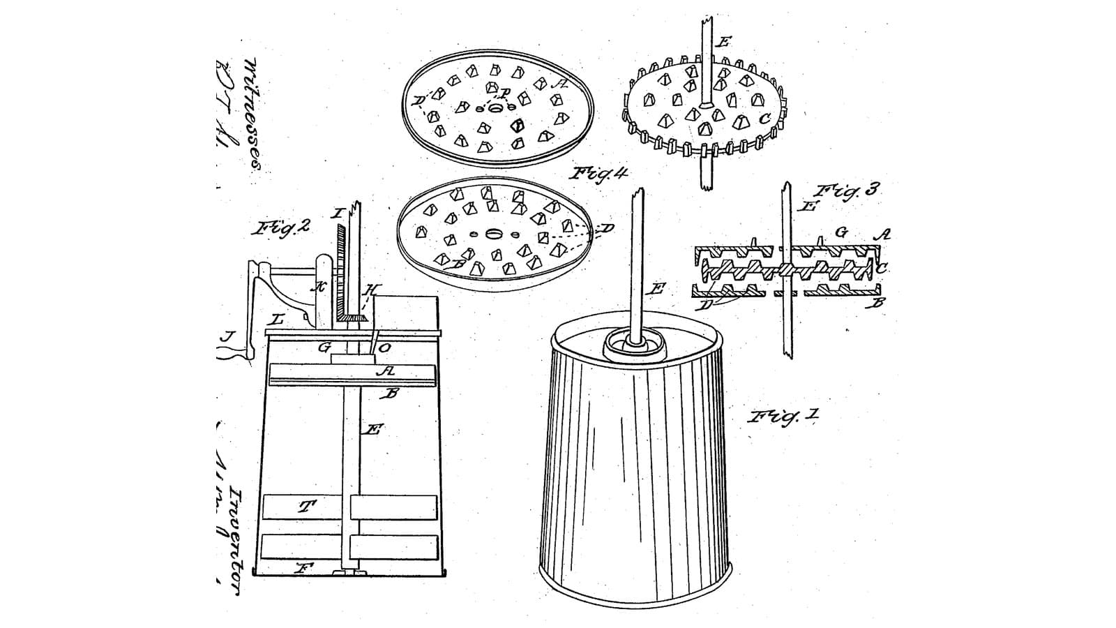
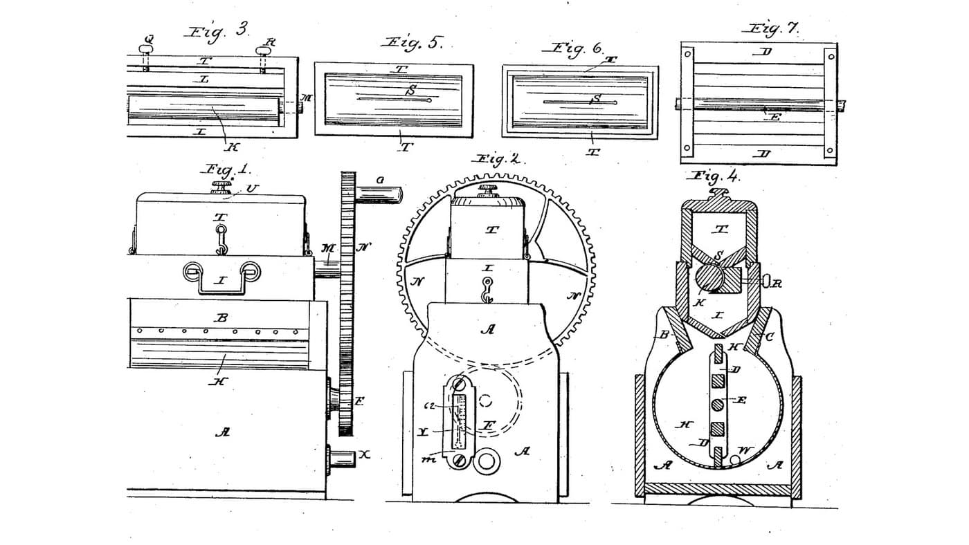
Jackson and Clarke grind the cream in a disk pack over the beaters. Fowler and Walter put the disks to one side and let one crank drive either disks or wings.
3

Read US 32,939

"By having the wheel H, attached to the bar G, and the latter arranged as shown, the disk b, may be rotated without the shaft B, or the latter may be rotated without the former or both rotated simultaneously as may be desired. This is an important feature of the invention for it is frequently necessary to use the disks without the wings or gatherers and vice versa."
4

Body A and lid

Glue up a hardwood box A 300 mm wide, 360 long and 320 deep inside, from 20 mm boards, joints sealed with silicone sealant. Bore one end 16.6 mm at 80 and 240 mm above the inside floor on its centre line for the shafts B and E, and the far end 16.6 mm at 80 mm for B's other bearing. Cut a hardwood lid with a 14 mm hole 25 mm off the centre line and 13 mm in from the geared end, for the hopper's spout.

Materiali per questo passaggio:

Tavola di legno duroTavola di legno duro4 pezzi
Colla da legnoColla da legno1 pezzo
Sigillante siliconicoSigillante siliconico1 pezzo
Viti da legnoViti da legno30 pezzi

Strumenti necessari:

Sega circolare da bancoSega circolare da banco
Trapano a batteriaTrapano a batteria
Serie di punte da trapanoSerie di punte da trapano
Set di punte a lanciaSet di punte a lancia
Morsetto a barraMorsetto a barra
Set di cacciavitiSet di cacciaviti
Metro a nastroMetro a nastro
5

Shaft B with wings C and pinion D

Cut a 16 mm stainless shaft B 432 mm long. Screw two pairs of hardwood wings C 70 x 80 x 20 mm through hardwood hubs on it, a quarter turn apart, one pair 70 to 150 mm from the geared end and one 220 to 300. Run it through both ends with shaft collars and pin a pinion D on its outer end 6 mm outside the box.

Materiali per questo passaggio:

Barra di acciaio inossidabileBarra di acciaio inossidabile1 pezzo
Tavola di legno duroTavola di legno duro1 pezzo
Viti da legnoViti da legno8 pezzi
Shaft CollarShaft Collar2 pezzi
CoppigliaCoppiglia2 pezzi
Filamento PETGFilamento PETG1 pezzo

Strumenti necessari:

Stampante 3D a filamento (FDM)Stampante 3D a filamento (FDM)
Sega circolare da bancoSega circolare da banco
Trapano a batteriaTrapano a batteria
Serie di punte da trapanoSerie di punte da trapano
Seghetto per metalliSeghetto per metalli
Lime (lima a mano)Lime (lima a mano)
Set di cacciavitiSet di cacciaviti
6

Print the pinions D and d (two)

A pinion: 16 teeth, module 2.5, 12 mm thick, 16.2 mm bore. Print two. PETG, 0.2 mm layers, 30 % infill, 4 walls.
File di designSTLCC0 - Free
7

Print the grinding disk b

The turning disk: 110 mm across, 6 thick, with two rings of ledges c 3 mm high at 40 and 50 mm out on its face, 16.2 mm bore. PETG, 0.2 mm layers, 30 % infill, 4 walls.
File di designSTLCC0 - Free
8

Print the hopper F

The hopper: a funnel 80 mm across on a 14 mm spout long enough to reach behind the fixed disk. PETG, 0.2 mm layers, 30 % infill, 4 walls.
File di designSTLCC0 - Free
9

Disks a and b, shaft E, pinion d and hopper F

Cut a 6 mm HDPE disk a 120 mm across with a 60 mm centre opening, glue twelve HDPE ribs 26 x 6 x 3 mm radially on its face, and screw it inside the geared end on three 10 mm stainless standoffs 25 mm long, around the upper shaft hole, ribs inward. Cut a 16 mm stainless shaft E 120 mm long, push it through the end and the disk a's opening, pin the disk b on its inner end with its ledges 3 mm from a's ribs, and the pinion d on its outer end. Set the hopper F in the lid so its spout drops into the space behind a, beside the shaft.

Materiali per questo passaggio:

Lastra di HDPELastra di HDPE1 pezzo
Colla da legnoColla da legno1 pezzo
Barra di acciaio inossidabileBarra di acciaio inossidabile2 pezzi
Viti da legnoViti da legno3 pezzi
CoppigliaCoppiglia2 pezzi
Shaft CollarShaft Collar1 pezzo
Filamento PETGFilamento PETG1 pezzo

Strumenti necessari:

Stampante 3D a filamento (FDM)Stampante 3D a filamento (FDM)
BussolaBussola
Seghetto alternativoSeghetto alternativo
Set di punte a lanciaSet di punte a lancia
Seghetto per metalliSeghetto per metalli
Trapano a batteriaTrapano a batteria
Serie di punte da trapanoSerie di punte da trapano
Set di cacciavitiSet di cacciaviti
10

Print the crank wheel H

The crank wheel: 48 teeth, module 2.5, 12 mm thick, 12.2 mm bore. PETG, 0.2 mm layers, 30 % infill, 4 walls.
File di designSTLCC0 - Free
11

Bar G, guides e, e', wheel H and pin a*

Cut a mild steel flat bar G 470 x 24 x 6 mm, drill it 12.2 mm for H's axle 210 mm from one end and a row of 6 mm holes near the other end. Make two hardwood guides: e, a block with a slot just wide enough for the bar, screwed to the geared end level with the gap between the pinions; e', with a slot 60 mm tall so the bar's end can rise and fall, and a row of 6 mm holes across it. Fit a 12 mm stainless axle in the bar, the wheel H on it between the two pinions, and a crank handle on H's face. Slide the bar into the guides and hold it with a 6 mm pin a* through e' and the bar.

Materiali per questo passaggio:

Piatto di acciaio dolcePiatto di acciaio dolce1 pezzo
Tavola di legno duroTavola di legno duro1 pezzo
Viti da legnoViti da legno8 pezzi
Barra di acciaio inossidabileBarra di acciaio inossidabile1 pezzo
CoppigliaCoppiglia2 pezzi
Tasselli di legno duroTasselli di legno duro1 pezzo
Filamento PETGFilamento PETG1 pezzo

Strumenti necessari:

Stampante 3D a filamento (FDM)Stampante 3D a filamento (FDM)
Seghetto per metalliSeghetto per metalli
Lime (lima a mano)Lime (lima a mano)
Morsa da bancoMorsa da banco
Trapano a batteriaTrapano a batteria
Serie di punte da trapanoSerie di punte da trapano
Serie di scalpelli da legnoSerie di scalpelli da legno
Set di cacciavitiSet di cacciaviti
12

The build in 3D

FreeCAD model of this build, half the box cut away: the wing shaft low in the box, the fixed ribbed disk and the turning ledged disk high at the geared end, the hopper, and outside the crank wheel on its bar in two guides, meshing both pinions.
File di designBLENDCC0 - Free
13

Churn: grind, then gather

Pin the bar so H meshes the disk's pinion d only. Turn the crank and pour about 12 litres of heavy cream at about 15 °C, checked with the thermometer, slowly into the hopper, timing it; it is ground between the disks and falls to the bottom. Then move the bar so H meshes the wings' pinion D (or both) and turn to gather the butter. Lift the lid, take out the butter, pour the buttermilk into a bowl, wash the butter in cold water until it runs clear, salt and weigh it.

Materiali per questo passaggio:

Panna da montarePanna da montare12 l
Sale marino grossoSale marino grosso1 pezzo
AcquaAcqua1 pezzo

Strumenti necessari:

Termometro a sonda permanenteTermometro a sonda permanente
CronometroCronometro
Bilancia digitale da cucinaBilancia digitale da cucina
Grande ciotola da impasto in acciaio inossidabileGrande ciotola da impasto in acciaio inossidabile
14

Troubleshooting

Shifting-gear churn troubleshooting.

Flow

Loading...
15

History and honest limits

**John Fowler** and **W. L. Walter** of Homer, Cortlandt County, New York, US 32,939, 30 July 1861, "Churn". They did not claim the disks or the wings, which were known, but "the arrangement of the sliding or adjustable bar G, with the wheel H, attached and arranged in relation with the pinions D, d, of the shaft B, and disk b". Their drawing shows H's crank as a pin on its face and a handle on the bar's end for shifting it. The patent gives no sizes; every size here is ours.

Materiali

14

Strumenti richiesti

18

File di progetto

5

CC0 Pubblico dominio

Questo progetto è rilasciato sotto CC0. Sei libero di copiare, modificare, distribuire e utilizzare quest'opera per qualsiasi scopo, senza chiedere permesso.

Supporta il Maker acquistando prodotti tramite il suo progetto dove guadagna una Commissione Maker stabilita dai venditori, oppure crea una nuova iterazione di questo progetto e includilo come collegamento nel tuo progetto per condividere i ricavi.

Commenti

(0)

Accedi per partecipare alla discussione

Caricamento commenti...