コラボレーション
アート
美容とウェルネス
工芸
文化と歴史
エンターテインメント
環境
食品と飲料
リバースエンジニアリング
科学
スポーツ
テクノロジー
ウェアラブル
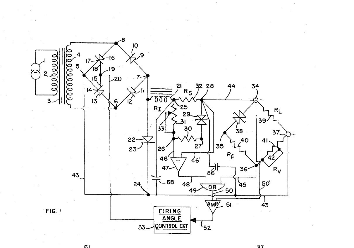


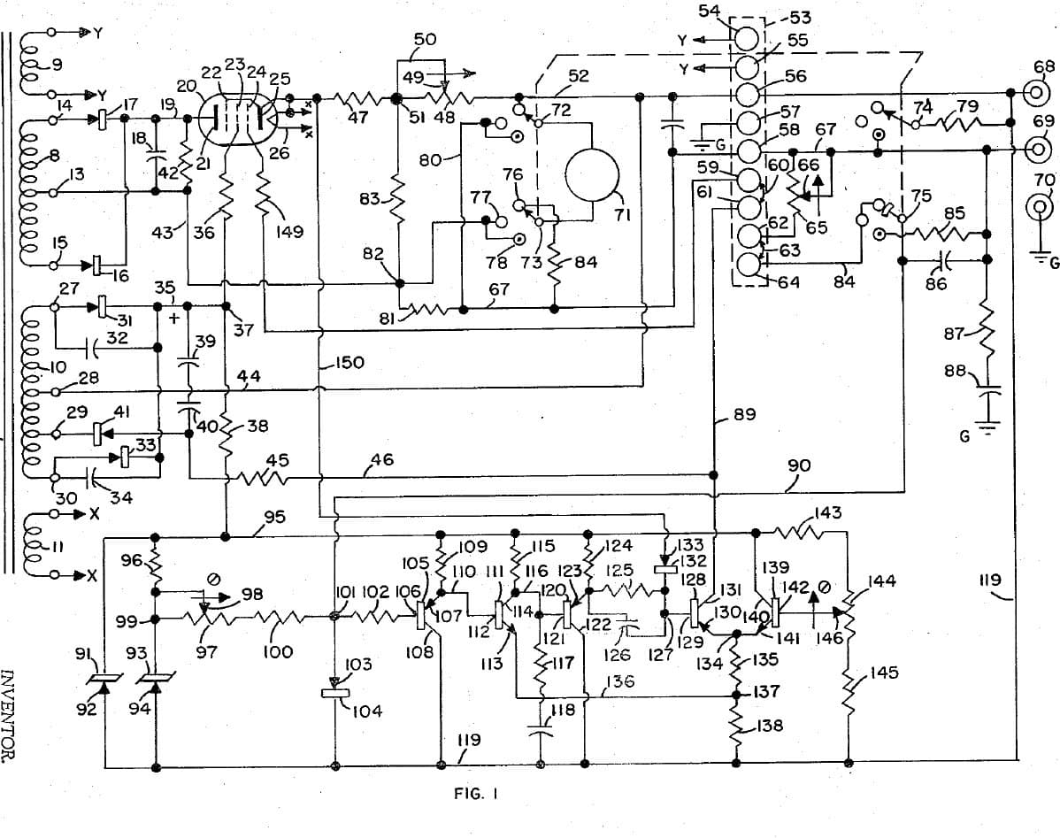
DC Power Supply: SCR-Regulated, Voltage and Current Bridges with Automatic Cross-Over (Kupferberg & Ash, Forbro, US 3,305,763, 1967)
A variable DC supply regulated by controlled rectifiers instead of a series transistor. Two of the four rectifiers in the bridge are silicon controlled rectifiers; how late in each half-cycle they are fired sets the output. A voltage bridge and a current bridge each make an error signal, an analog OR gate passes whichever is larger, and the supply crosses over automatically between holding the voltage and holding the current.
Result: a variable voltage / current regulated DC supply with automatic cross-over.
Source: K. Kupferberg and J. Ash (Forbro Design), US 3,305,763 (1967), Fig. 1. Unknown: component values and the firing-angle circuit. Picture: the patent drawing.
上級者
Unknown
手順
1
1
Build the controlled rectifier bridge
Build the controlled rectifier bridge
In a case, wire the cord through a switch and fuse to a transformer. Feed its secondary into a bridge of two ordinary rectifiers and two silicon controlled rectifiers. Smooth the negative output through a choke and a capacitor, then through a current-sensing resistor (with a second capacitor forming a further filter) to the negative output terminal; the positive goes straight to the positive terminal. Ours: the case, switch and fuse. Not given: the ratings.
このステップの材料:
 アルミ筐体箱1 個
 プラグ付きコード1 個
 トグルスイッチ1 個
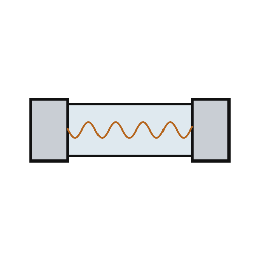 ヒューズ1 個
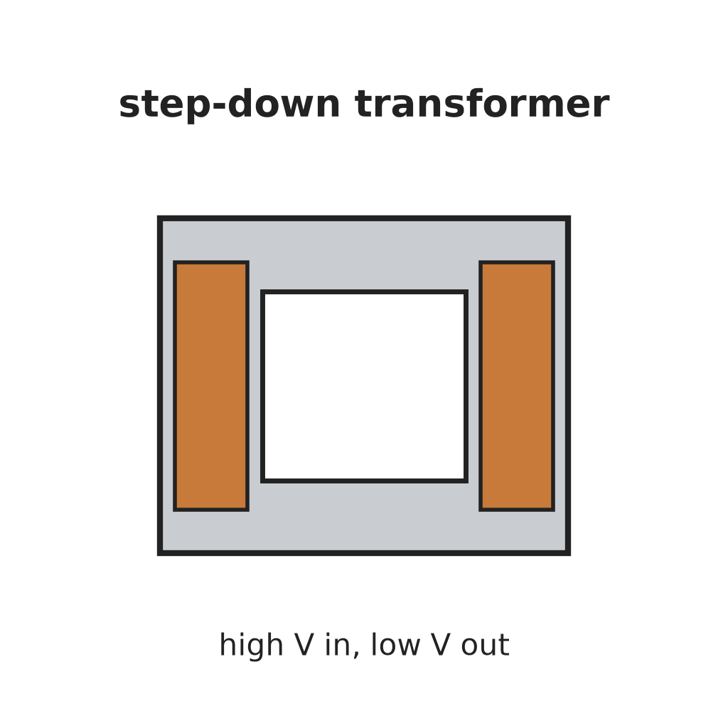 降圧トランス1 個
 ダイオード2 個
 サイリスタ(SCR)2 個
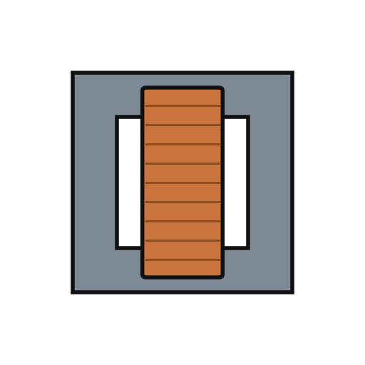 チョークコイル(平滑用)1 個
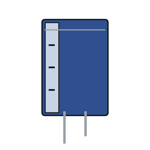 電解コンデンサ2 個
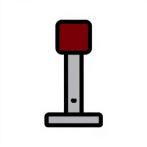 バインディングポスト2 output + and -
必要な工具:
 ハンドドリル
 ドライバーセット
2
2
Build the two bridges
Build the two bridges
Current bridge: the sensing resistor, a reference Zener, a fixed resistor and the variable current-control resistor. Voltage bridge: the load across the output, the variable voltage-control resistor, a fixed resistor and a second reference Zener. Feed both Zeners from a small separate supply. Not given: the values, the Zener supply.
このステップの材料:
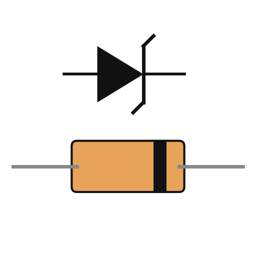 ツェナーダイオード2 個
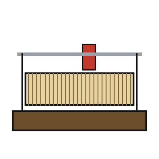 レオスタット2 voltage and current controls
 電気抵抗1 sensing and bridge resistors
必要な工具:
 はんだごて
3
3
Build the control chain and use it
Build the control chain and use it
Invert the current bridge's error in a phase-reversing amplifier and feed it, with the voltage bridge's error, to an analog OR gate that passes the larger. Amplify the result and feed it to a firing-angle control circuit that fires the two controlled rectifiers' gates later or earlier in each half-cycle. In use, set the voltage and the current: for any load larger than the cross-over resistance (voltage setting divided by current setting) the supply holds the voltage, for a smaller one the current. Not given: the amplifier, OR-gate and firing circuits in this form.
このステップの材料:
 プリント基板1 個
 トランジスター詰め合わせ1 amplifiers
 不明な材料1 OR gate and firing-angle circuit
 はんだ線1 as needed
必要な工具:
はんだごて材料
17- 1 個プレースホルダー
- 1 個プレースホルダー
- プレースホルダー
- 1 個プレースホルダー
- 1 個プレースホルダー
- 2 個プレースホルダー
- 2 個プレースホルダー
- 1 個プレースホルダー
- 2 個プレースホルダー
- プレースホルダー
- 2 個プレースホルダー
- 2 voltage and current controlsプレースホルダー
- 1 sensing and bridge resistorsプレースホルダー
- 1 個プレースホルダー
- 1 amplifiersプレースホルダー
- 1 OR gate and firing-angle circuitプレースホルダー
- 1 as neededプレースホルダー
この設計図で作るもの

関連ブループリント
これらのブループリントは知識を共有しています — 技術、材料、原理
CC0 パブリックドメイン
このブループリントはCC0で公開されています。許可を求めずに、自由にコピー、修正、配布、あらゆる目的で使用できます。
メイカーを応援するには、ブループリント経由で製品を購入してください。メイカーには メイカーコミッション がベンダーにより設定されています。または、このブループリントの新しいイテレーションを作成し、自分のブループリントにコネクションとして含めて収益を共有できます。