アート
美容とウェルネス
工芸
文化と歴史
エンターテインメント
環境
食品と飲料
リバースエンジニアリング
科学
スポーツ
テクノロジー
ウェアラブル



Designing for the Mould: Draft, Wall and the Ejector
A moulded part is not a shape that happens to be plastic. It is a shape that had to come out of a steel box, in one direction, while shrinking onto the thing it was formed around.
Almost every rule in moulding design follows from those three facts: **draft** so it can release, **uniform thin walls** so it cools evenly and fast, **ribs instead of thickness** so it is stiff without a sink mark, and a **parting line** that lets the two halves separate at all.
This rung is a sibling to the injection moulding blueprint, not a repeat of it: that one cuts a mould and shoots parts. This one tests the design rules **on printed parts**, because a 3D printer will happily make the zero-draft, thick-walled, fat-ribbed part that no mould could ever release — which makes it the ideal way to see what each rule is actually for.
中級者
About 4 hours, plus print time
手順
1
1
Read a moulded part and find every rule already obeyed
Read a moulded part and find every rule already obeyed
Pick up any moulded plastic object — a bottle crate, a tool case, the inside of an appliance — and turn it over. Everything in this rung is on it, and finding the features yourself is worth more than reading the list.
Find, and write down where each one is:
- **The parting line.** A fine seam running all the way round. Everything on one side of it came out of one mould half. Ask yourself which direction the mould opened, then check that nothing on the part would have blocked it.
- **Ejector pin marks.** Round, slightly proud or slightly sunk discs, always on the inside or the hidden face. Count them; their number and spread tell you how hard the part was to push off.
- **The gate.** A small scar where the melt entered, often trimmed. Follow the wall away from it and you are following the direction the plastic flowed.
- **Draft.** Stand a straightedge against an internal wall. It is not parallel to the opening direction — it leans, by a degree or two.
- **Ribs.** Thin, tall, on the hidden side, and noticeably thinner than the wall they stiffen. Measure both with the calipers and take the ratio.
- **A sink mark**, if the designer got that ratio wrong: a shallow dimple on the show face, exactly opposite a rib or a boss.
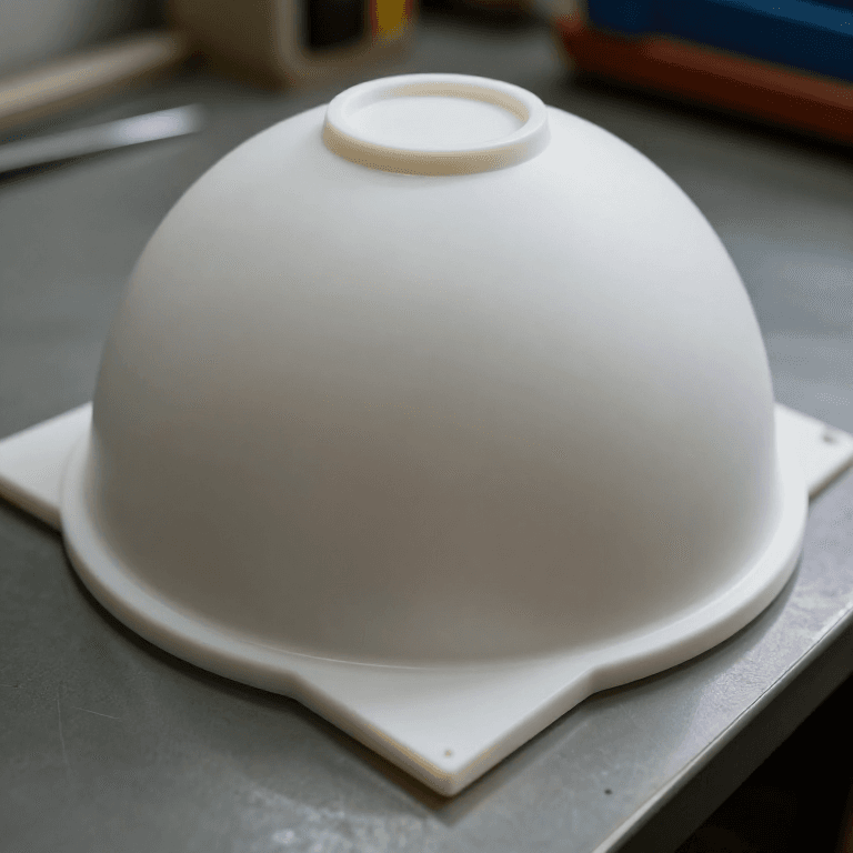
The photograph on this page is two cavities' worth of a moulding still joined by its runner — the channel that fed both parts. On a production part that runner is snapped off and the gate scar is all that is left of it.
必要な工具:
 デジタルノギス 6インチ
 定規
定規 デジタル顕微鏡
2
2
Print the draft test, and try to pull the parts apart
Print the draft test, and try to pull the parts apart
Design one test part and print it several times: a simple open box, 40 mm deep, 30 mm square inside, 2 mm wall — and a matching solid core to sit in it. Print the box five times with the **inside** walls drafted at 0°, 0.5°, 1°, 2° and 3°.
Slide each box onto the same core, warm the assembly gently with the heat gun so the plastic relaxes onto it, let it cool fully, and then measure the force to pull it off with the spring scale.
This is not a moulding simulation — printed PLA shrinks differently from moulded polypropylene — but the *shape* of the result is the real one, and it is stark. The 0° box needs many times the force of the 2° box, and the 0° box is the one that marks, whitens or tears when it finally lets go.
Do it once more with a **textured** inside face — print one box with a coarse surface pattern — and note that the texture behaves like an undercut: it needs its own extra draft on top of whatever the wall needed. Step 5 gives the rule of about a degree per 0.025 mm of texture depth.
Record force against draft angle on graph paper. Tape it inside your notebook; this is the single chart that makes 'why does everything have draft' obvious for good.
このステップの材料:
 PLA フィラメント1 個
 PETGフィラメント1 個
必要な工具:
 3D プリンター
 ばねばかり(力計)デジタルノギス 6インチ
 ヒートガン
ヒートガン 万力(ベンチバイス)
 方眼紙
方眼紙 透明保護メガネ
 実験ノート(複写式)
3
3
Print the rib ladder and find the sink
Print the rib ladder and find the sink
A rib is how you get stiffness without thickness, and it is the commonest place a beginner produces a visible defect.
Print a flat plate 2 mm thick and 120 mm long, with six ribs across its back, 6 mm tall, at thicknesses of 0.4, 0.6, 0.8, 1.0, 1.4 and 2.0 mm. Print it in a **glossy** filament, because a sink mark on a matt surface is much harder to see.
Then look at the front face under raking light — a lamp almost edge-on to the surface. The thin ribs leave nothing. Somewhere around 0.6 to 0.8 of the wall thickness a shallow trough appears opposite each rib, and by 1.0 it is unmistakable.
A printer does not shrink the way a moulding does, so what you are seeing here is partly the printer's own thermal contraction — but the mechanism is identical and so is the rule. **The thick place freezes last, and the surface is pulled in behind it.**
Now test the stiffness side of the trade. Support each ribbed section at its ends and hang a weight from the middle, measuring deflection. Compare a tall thin rib against a short fat one of the same cross-section area. The tall one is far stiffer, because — exactly as in the corrugated-roof rung of the sheet metal batch — stiffness follows how far the material sits from the neutral axis, and height buys that squared while thickness buys it once.
That is the whole design answer: **taller and more numerous, never fatter.**
このステップの材料:
PLA フィラメント1 個 ABS フィラメント1 個
必要な工具:
3D プリンターデジタルノギス 6インチデジタル顕微鏡 デジタルスケール定規方眼紙透明保護メガネ実験ノート(複写式)
4
4
Find an undercut, and then design it away
Find an undercut, and then design it away
An **undercut** is any feature that would stop the part leaving the mould in the opening direction: a side hole, an external snap lip, a groove round the outside, a boss that overhangs.
Undercuts are not forbidden — they are *expensive*, because releasing them needs a moving part in the tool: a side-action slide driven by an angle pin, a collapsing core, or an unscrewing mechanism for a thread. Each one adds cost, cycle time and something that can go wrong.
Take your test box and put a snap lip on the outside, then hold a flat card against the box and try to move it straight up. The lip stops it. That is an undercut, demonstrated in two seconds.
Now design it away, which is the skill worth having. Three moves, in order of preference:
1. **Pass-through.** Put a hole in the face above the snap lip so the mould half above can reach down and form the underside of the lip directly. Almost every moulded snap fit you have ever seen has this window above it, and now you know why.
2. **Move the parting line.** If the feature sits on the parting line it is formed by the two halves closing, not by either one withdrawing.
3. **Split the part.** Two simple mouldings joined later — which is rung 5's subject — often beat one clever one.
Print both versions, the undercut one and the pass-through one, and put them side by side. That pair explains more about why plastic products look the way they do than any amount of reading.
このステップの材料:
PLA フィラメント1 個必要な工具:
3D プリンターデジタルノギス 6インチ クラフトナイフ
 バリ取り工具デジタル顕微鏡透明保護メガネ
5
5
Cooling time, draft and the rib ratio
Cooling time, draft and the rib ratio
Jupyter ノートブックを読み込み中…
必要な工具:
方眼紙6
6
History and context
History and context
**Attribution, stated honestly.** No patent is claimed for this rung and none should be. Draft, uniform walls, rib ratios and parting lines are trade knowledge, worked out independently in every moulding shop and written into company design manuals rather than into filings. What is worth naming is that they are **not conventions** — each one is a consequence with a number behind it, and step 5 is those numbers.
**Where the rules come from.** They are older than plastics. Draft is why a sand casting pattern is tapered, and the pattern-maker's rule long predates any polymer; the die casting rung in the catalogue obeys exactly the same three constraints for the same three reasons. What changed with thermoplastics is the **cooling time**, because a polymer conducts heat so badly that the wall thickness stops being a strength decision and becomes an economic one.
**The idea to keep.** In moulding, *thickness is time*. A designer who adds a millimetre to a wall has added seconds to every part ever made from that tool, and nothing downstream can recover it. That single fact explains the shell-and-rib shape of nearly every moulded object you own, and it is the reason a well-designed plastic part is so counterintuitively thin.
**Honest limits.** Everything above is tested here on printed parts, and a printed part is not a moulding: it shrinks anisotropically, it is layered, and it has no ejection at all. The printer is a way to *see the rules operating*, not a substitute for a tool trial. Real shrinkage figures are supplier data for a specific grade, not the round numbers in step 5, and a part with a tight tolerance is always proved on a first-off sample rather than calculated.
材料
3- 3 個プレースホルダー
- 1 個プレースホルダー
- 1 個プレースホルダー
必要な工具
13- プレースホルダー
- プレースホルダー
- プレースホルダー
- プレースホルダー
- プレースホルダー
- 1 vendor sell this, none ship to you yetプレースホルダー
- プレースホルダー
- プレースホルダー
- プレースホルダー
- 実験ノート(複写式)10%コミッションプレースホルダー
- プレースホルダー
- プレースホルダー
- プレースホルダー
関連ブループリント
これらのブループリントは知識を共有しています — 技術、材料、原理



CC0 パブリックドメイン
このブループリントはCC0で公開されています。許可を求めずに、自由にコピー、修正、配布、あらゆる目的で使用できます。
メイカーを応援するには、ブループリント経由で製品を購入してください。メイカーには メイカーコミッション がベンダーにより設定されています。または、このブループリントの新しいイテレーションを作成し、自分のブループリントにコネクションとして含めて収益を共有できます。