コラボレーション
アート
美容とウェルネス
工芸
文化と歴史
エンターテインメント
環境
食品と飲料
リバースエンジニアリング
科学
スポーツ
テクノロジー
ウェアラブル
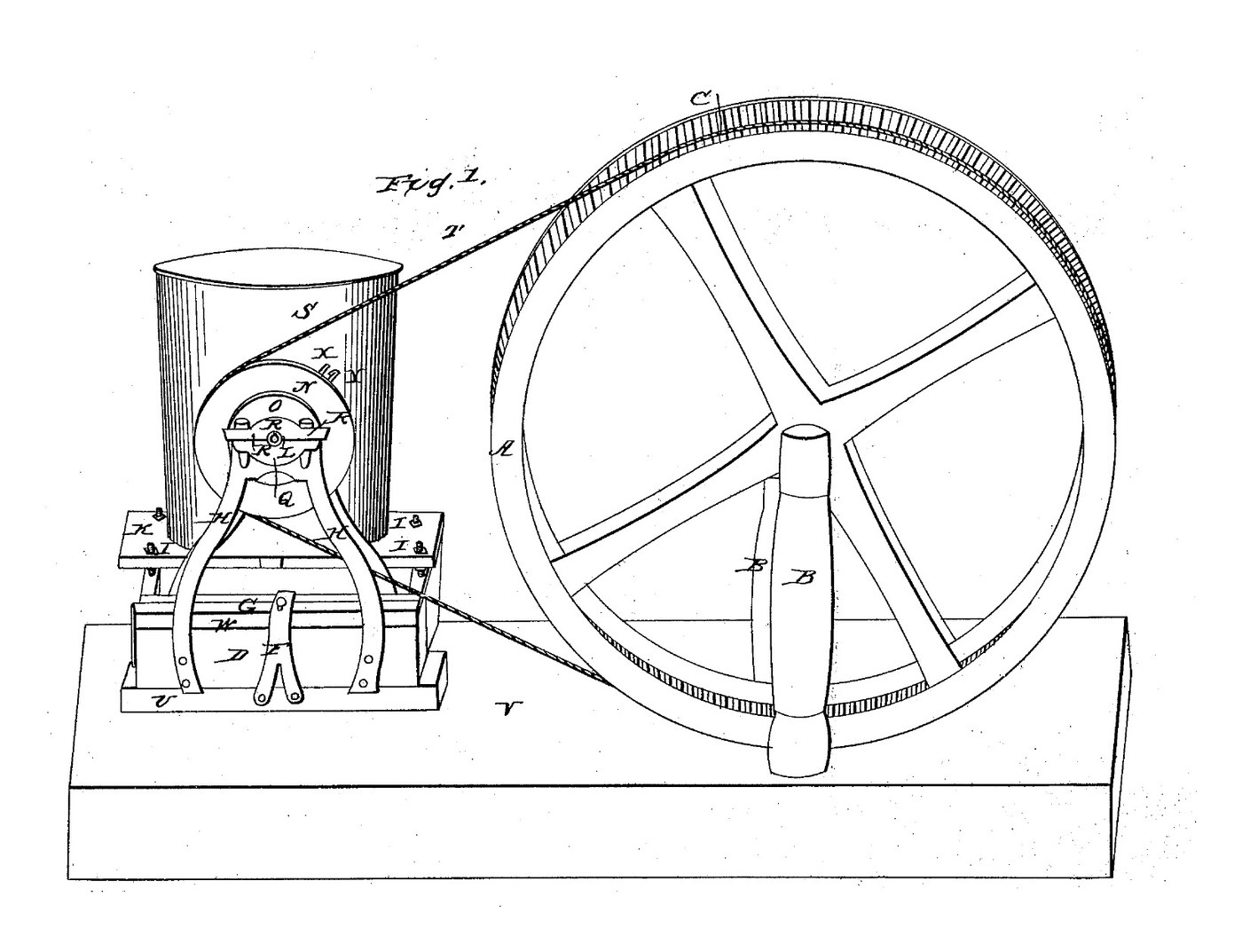


Sliding-Head Churn Drive: The Churn Rides on the Pulley Head and Stays in Line When the Belt Is Slacked
Joseph Forsyth of Wheeling, Virginia, received US 22,022, dated 9 November 1858, for working a churn by power from a big belt wheel. The pulley head slides along a guide block to tighten or slack the belt, which starts or stops the churn. The churn stands on a carriage fixed to the head, so its shaft stays in line with the pulley's. A platform on four screws raises or lowers different churns to the pulley's height.
This rung builds it full size with a hand-cranked wheel and a rope belt.
中級者
About 2 days
手順
1
1
Speed, rope and slack
Speed, rope and slack
Jupyter ノートブックを読み込み中…
2
2
Churns worked by power, before it
Churns worked by power, before it
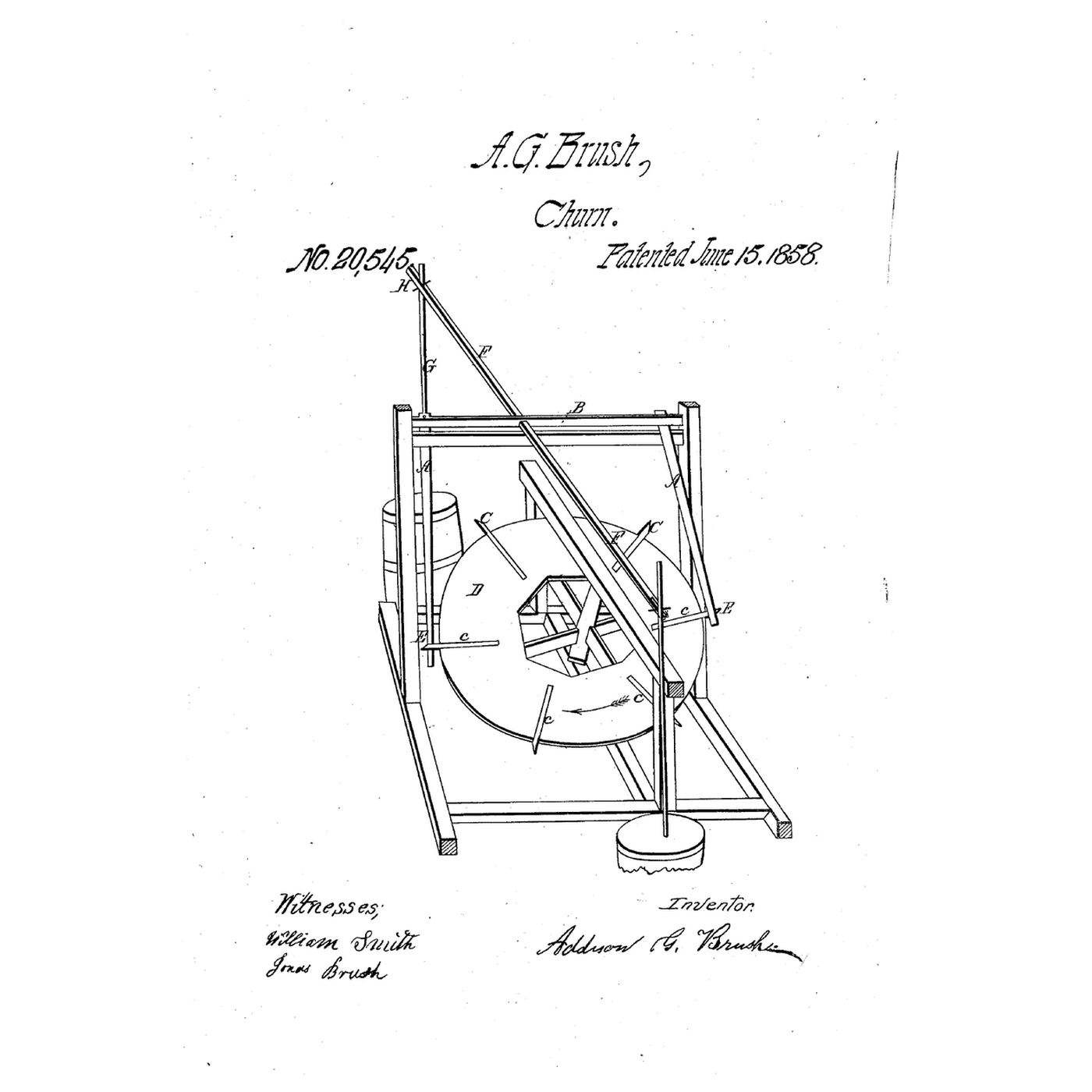
Brush worked a dasher from a dog's tread-wheel. Forsyth turns a crank churn by a belt and stops it by slacking the belt.
3
3
Read US 22,022
Read US 22,022
"The nature of my invention consists, first, in combining the carriage D with the movable pulley head H H in such a manner that the said carriage will move with the head when it is required to stop or start the motion of the churn, thereby enabling me to keep the shafts of the pulley, and churn in line."
4
4
Wheel A and posts B
Wheel A and posts B
Cut a plywood disc 1160 mm across and two discs 1200 mm across from 18 mm plywood. Glue and screw a larger disc to each face of the smaller one: the gap between them is the rope groove C. Screw a 160 mm hub block on each side. Stand two 70 mm posts 730 mm tall on 900 mm sills, 150 mm apart, each with two braces. Bolt a flange bearing on each post's outer face, 700 mm up, and run a 30 mm shaft M through bearings, posts and wheel, cross-bolted to the hub.
このステップの材料:
 合板3 個
 木工用接着剤1 個
 #8 × 1 インチ木ねじ60 個
 針葉樹材 70x70 mm4 個
 #10 x 3" 木ねじ24 個
 フランジ軸受2 個
 鋼製シャフト 30 mm1 個
 六角ボルト一式 M105 個
必要な工具:
 ジグソー
 手のこぎり
 コードレスドリル
 ドリルビットセット
 スペードビットセット
 クランプ
 モンキーレンチ
 水準器
 メジャー(巻尺)
5
5
Crank
Crank
How the wheel is turned is not given; ours has a crank. Bolt a hardwood arm 350 x 70 x 30 mm on shaft M outside one bearing and glue a 30 mm dowel 150 mm long into it 280 mm from the shaft as the handle.
このステップの材料:
 堅木の板1 個
 堅木のダボ1 個木工用接着剤1 個六角ボルト一式 M101 個
必要な工具:
手のこぎりコードレスドリルスペードビットセット 紙やすりモンキーレンチ
6
6
Guide block and pulley head
Guide block and pulley head
Screw a 900 mm guide block U of 70 mm timber to the floor in line with the wheel, 1300 mm from shaft M. Lay a 400 mm head block on it. Cut two frames H from 50 x 8 mm flat bar, 420 mm long, and bolt them to the head block's sides so their ends run down the guide block's sides. Bolt a flange bearing on each frame's outer face 400 mm up. Make the pulley O like the wheel: a 200 mm disc between two 240 mm rings. Fit it on a 30 mm shaft through the bearings.
このステップの材料:
針葉樹材 70x70 mm2 個#10 x 3" 木ねじ8 個 軟鋼平鋼2 個六角ボルト一式 M104 個フランジ軸受2 個鋼製シャフト 30 mm1 個合板1 個木工用接着剤1 個#8 × 1 インチ木ねじ12 個
必要な工具:
 金切りのこ(ハクソー)
 やすり(手やすり)
 万力(ベンチバイス)コードレスドリルドリルビットセットジグソーモンキーレンチ
7
7
Strap F and thumb screw E
Strap F and thumb screw E
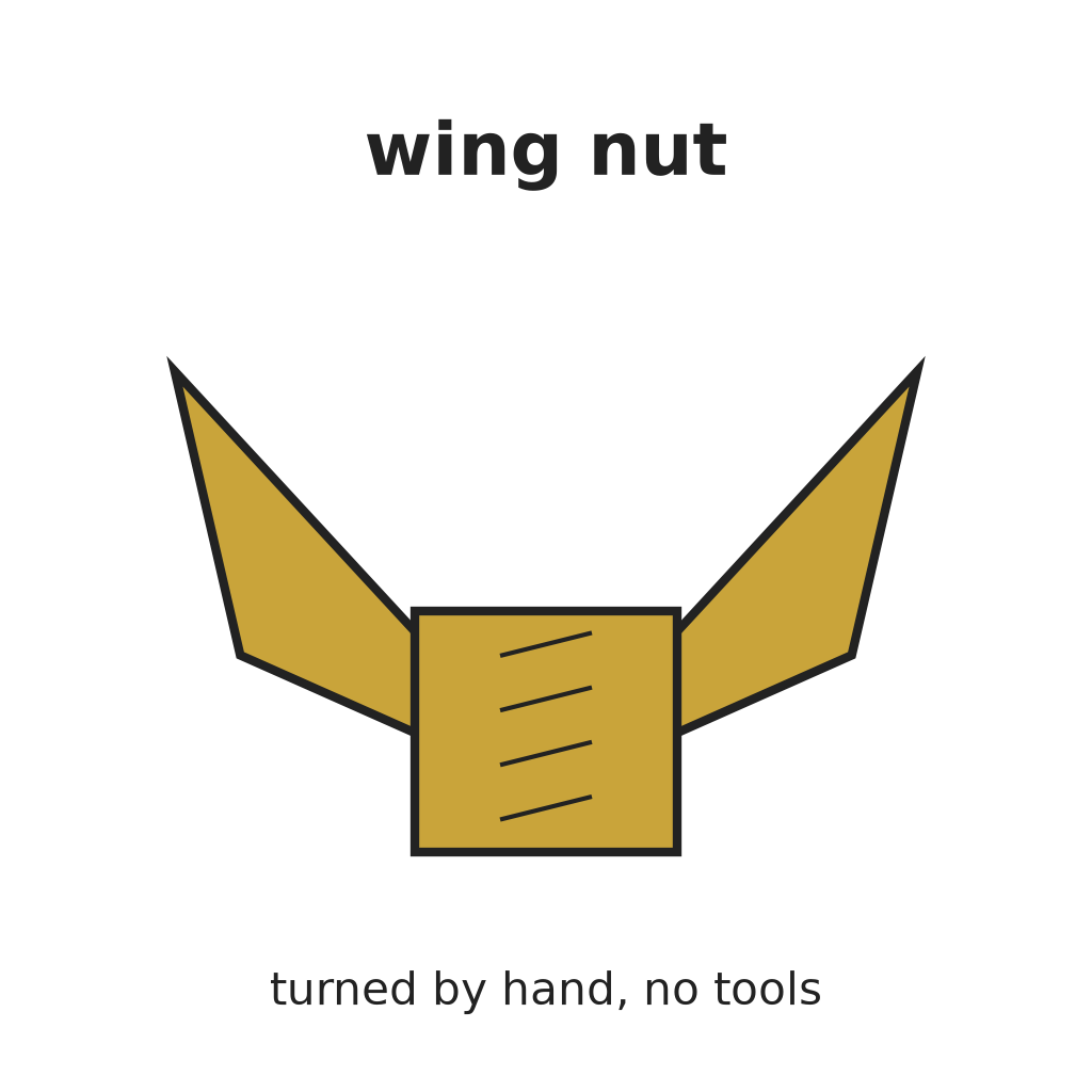
Bend a 30 x 5 mm flat bar into a bridge over the head block, 80 mm from the frames, and screw its legs to the guide block's sides. Drill its top for an M8 rod, run a nut onto the rod under the strap, and lock a wing nut on top as the thumb screw. Turn it down to clamp the head block.
このステップの材料:
軟鋼平鋼1 個#8 × 1 インチ木ねじ4 個 全ねじ棒1 個
 六角ナット2 個
 ウイングナット1 個
必要な工具:
万力(ベンチバイス)金切りのこ(ハクソー)コードレスドリルドリルビットセット8
8
Carriage D and platform K
Carriage D and platform K
Bolt two 70 mm side bars, 865 mm long, to the head block's side, 330 mm apart, and join their far ends with a cross tie with a caster under its middle as the roller. Drill each bar twice for M12 rods (screws I), 360 mm apart; fix each rod with a nut above and below the bar. Run a nut down each rod, lay an 18 mm plywood platform 430 x 440 mm on them, and lock it with a second nut on top.
このステップの材料:
針葉樹材 70x70 mm2 個六角ボルト一式 M104 個 キャスターセット1 個全ねじ棒4 個六角ナット16 個
 平ワッシャー8 個合板1 個
必要な工具:
手のこぎりコードレスドリルドリルビットセットモンキーレンチ水準器9
9
Arm X and the rope belt
Arm X and the rope belt
Bolt a 140 mm flat-bar arm X with a 20 mm slot to a collar on the pulley shaft's end. Stand a crank churn on the platform and raise or lower the platform's nuts until its crank shaft is level with the pulley shaft and its handle V sits in the slot. Splice 12 mm cotton rope into a loop about 5 m long round both grooves (see the notebook), with the head slid towards the wheel.
このステップの材料:
軟鋼平鋼1 個六角ボルト一式 M101 個 ナイロンナット(ゆるみ止め)1 個
 綿の綱6 m
必要な工具:
金切りのこ(ハクソー)やすり(手やすり)コードレスドリルドリルビットセットモンキーレンチメジャー(巻尺)10
10
The build in 3D
The build in 3D
FreeCAD model of this build: the wheel on its posts with the crank, the guide block, pulley head, strap and thumb screw, the carriage with its caster, platform K on its four screws, a stand-in churn and arm X. The rope is not drawn.
11
11
Churn
Churn
Pour about 10 litres of heavy cream at about 15 °C into the churn. Slide the head away from the wheel until the rope is tight and clamp it with the thumb screw. Turn the wheel steadily, about 10 times a minute, and time it. To stop, loosen the thumb screw and slide the head towards the wheel: the carriage and churn move with it. When the butter comes, pour off the buttermilk, wash the butter in cold water until it runs clear, work in a pinch of salt and weigh it.
このステップの材料:
 生クリーム10 l
 粗い海塩1 個
 水1 個
必要な工具:
 バター撹拌器
 差しっぱなしのプローブ温度計
 ストップウォッチ
 デジタルキッチンスケール
 ステンレス鋼の大きな混ぜ鉢
12
12
Troubleshooting
Troubleshooting
Churn drive troubleshooting.
Flow
Loading...
13
13
History and honest limits
History and honest limits
**Joseph Forsyth** of Wheeling, Ohio County, Virginia (now West Virginia), US 22,022, 9 November 1858, "Operating Churns". He claimed the carriage D combined with the movable platform K. He gave no sizes, named only the "metallic" frames H, and did not say what turns wheel A or what the belt is: our hand crank, plywood wheel and pulley, cotton rope, timber, bearings, rods and caster are ours.
材料
21- 3 個プレースホルダー
- 3 個プレースホルダー
- 76 個プレースホルダー
- プレースホルダー
- 32 個プレースホルダー
- 2 個プレースホルダー
- 1 個プレースホルダー
- 15 個プレースホルダー
- 1 個プレースホルダー
- 1 個プレースホルダー
- 2 個プレースホルダー
- 4 個プレースホルダー
- 18 個プレースホルダー
- 1 個プレースホルダー
- 1 個プレースホルダー
- 8 個プレースホルダー
- プレースホルダー
- 6 mプレースホルダー
- 10 lプレースホルダー
- 1 個プレースホルダー
- 1 個プレースホルダー
必要な工具
18- 1 vendor sell this, none ship to you yetプレースホルダー
- プレースホルダー
- 1 vendor sell this, none ship to you yetプレースホルダー
- プレースホルダー
- プレースホルダー
- プレースホルダー
- プレースホルダー
- プレースホルダー
- 1 vendor sell this, none ship to you yetプレースホルダー
- プレースホルダー
- プレースホルダー
- プレースホルダー
- プレースホルダー
- プレースホルダー
- プレースホルダー
- プレースホルダー
- プレースホルダー
- プレースホルダー
設計ファイル
1

関連ブループリント
これらのブループリントは知識を共有しています — 技術、材料、原理


CC0 パブリックドメイン
このブループリントはCC0で公開されています。許可を求めずに、自由にコピー、修正、配布、あらゆる目的で使用できます。
メイカーを応援するには、ブループリント経由で製品を購入してください。メイカーには メイカーコミッション がベンダーにより設定されています。または、このブループリントの新しいイテレーションを作成し、自分のブループリントにコネクションとして含めて収益を共有できます。