コラボレーション
アート
美容とウェルネス
工芸
文化と歴史
エンターテインメント
環境
食品と飲料
リバースエンジニアリング
科学
スポーツ
テクノロジー
ウェアラブル
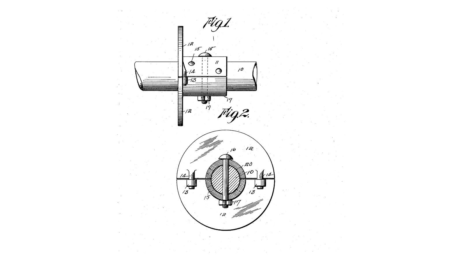


Divisible Flanged Shaft Collar: Two Halves Locked by Lugs, Bolted Through the Shaft in One of Three Hole Pairs (Obey, 1916)
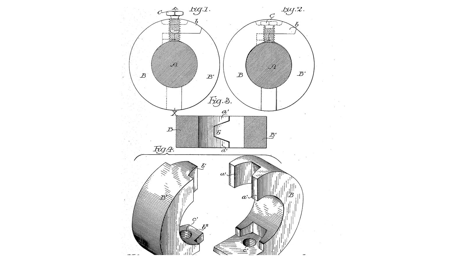
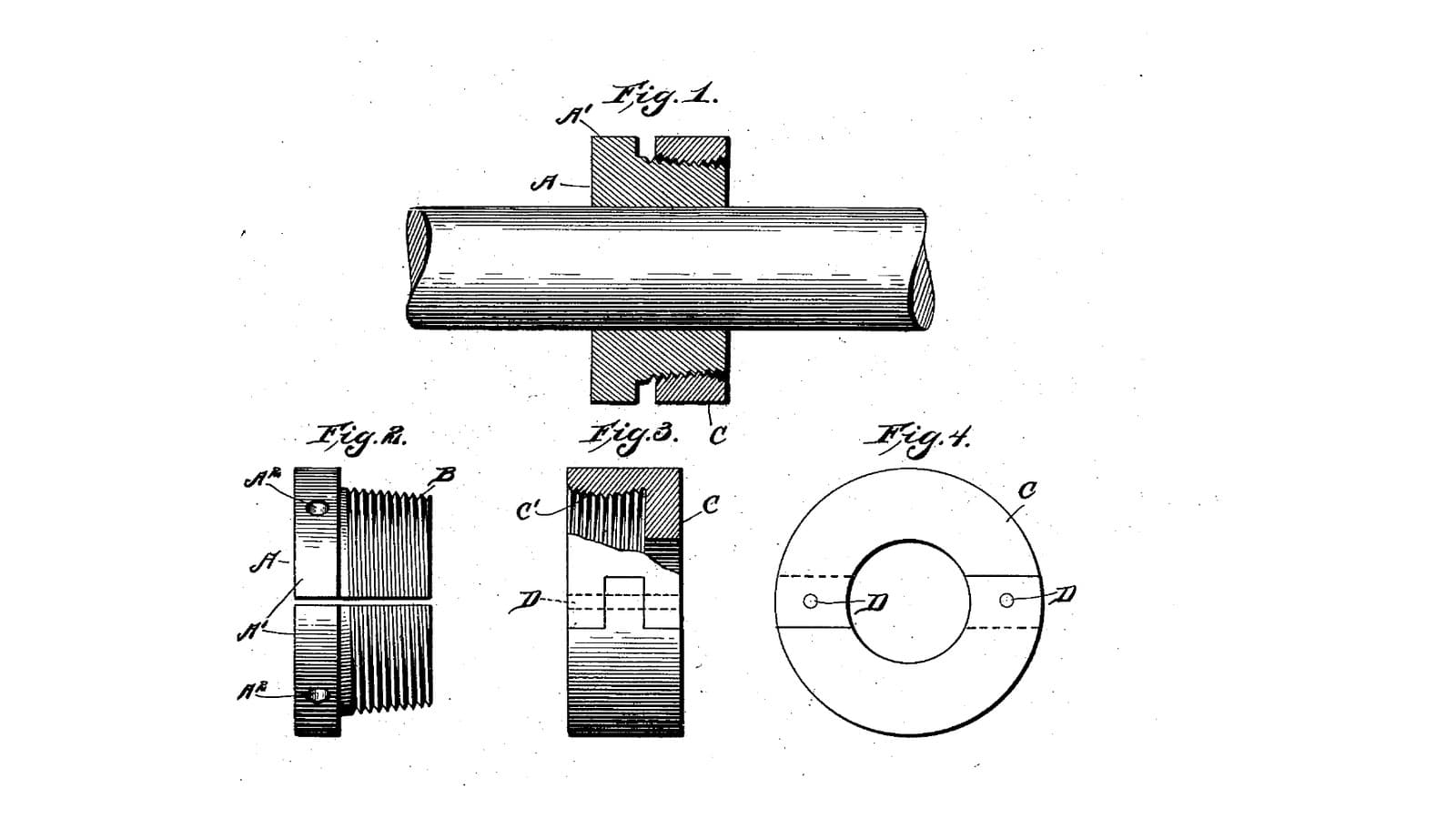
James F. Obey of Centerville, Iowa, received US 1,201,863, dated 17 October 1916, for a flanged collar that comes in two halves. It was meant for the chain rods of railway dump cars, whose collars often broke, and a whole rod then had to come out of its bearings. Lugs on one half of the flange go into slots in the other. A bolt through the rod's own hole and through a pair of openings in the collar holds it, with a nut. The collar has several pairs at different places, so it can be set in more than one position.
We turn ours in one piece and saw it in half. The patent gives no sizes; every size here is ours.
中級者
About 6 hours
手順
1
1
Where each pair of openings puts the collar
Where each pair of openings puts the collar
Jupyter ノートブックを読み込み中…
2
2
Read US 1,201,863
Read US 1,201,863
"These shaft collars frequently become broken and it is one of the important purposes of my invention to provide a shaft-collar which can be quickly and easily installed on the shaft without the removal of the shaft from its bearings."
3
3
Turn the flanged collar
Turn the flanged collar
Grip 75 mm round bar in the 3-jaw chuck. Face it and turn the flange to 70 mm. Turn the hub to 32 mm for 40 mm, leaving the flange 10 mm thick. Centre-drill, drill through 15 mm and ream 16 mm. Part off at 50 mm and face the flange's outer face.
このステップの材料:
 軟鋼丸棒1 個
 切削油1 個
必要な工具:
 金属旋盤
 三つ爪旋盤チャック
 旋盤の切削工具
 突切りバイト
 センタードリルセット
 ドリルビットセット
 リーマ
 デジタルノギス 6インチ
 保護めがね
4
4
Mark out and drill the holes
Mark out and drill the holes
Blue the flange and hub. Scribe the split line across the flange through the centre and along both sides of the hub. Mark two chord holes across the split line, 28 mm each side of the centre, in the middle of the flange's thickness; drill them 5 mm right through the flange, square to the split line. Mark three pairs of openings round the hub, at 18, 30 and 42 mm from the flange's outer face and at 90, 30 and 150 degrees from the split line. Centre-punch, and with the collar in the V-block drill each pair 6.5 mm straight through the hub and the bore.
必要な工具:
 青色当たり出し剤
 けがき針
 組み合わせスコヤ
 分度器
 センターポンチ
 ボール盤
 マシンバイス
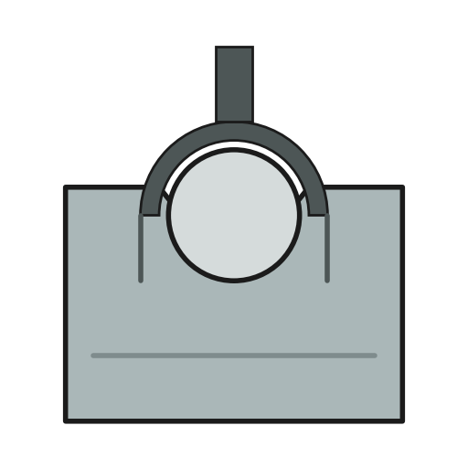 V ブロックドリルビットセットデジタルノギス 6インチ
5
5
Saw it in half and fit the lugs
Saw it in half and fit the lugs
In soft jaws, saw down the split line through flange and hub with a fine hacksaw blade, through the middle of the chord holes. File the cut faces flat. Tap a 5 mm steel dowel pin 20 mm long into each chord hole of one half, leaving 9 mm sticking out: these are the lugs, and the other half's holes are the slots. Put the halves together: they must close with only the saw cut between them, and slide apart only straight.
このステップの材料:
 鋼製ダウエルピン2 個
必要な工具:
 万力(ベンチバイス)
 万力の保護口金
 金切りのこ(ハクソー)
 ヤスリセット
 片手ハンマー(球頭)
 バリ取り工具
6
6
The collar in 3D
The collar in 3D
FreeCAD model, our sizes: the two halves with flange and hub on a 16 mm shaft, the two pins across the split in the flange, the three pairs of openings, and the M6 bolt and nut through the first pair and the shaft.
7
7
Drill the shaft and fit the collar
Drill the shaft and fit the collar
Mark where the collar's flange must stand and drill a 6.5 mm hole straight across the shaft, 18 mm from that mark, with the shaft in the V-block. Put the two halves round the shaft from the sides, the lugs into the slots, and turn the collar until the 18 mm pair lines up with the hole. Push an M6 x 50 bolt through and tighten a nyloc nut on it. To move the collar, take the bolt out, slide and turn the collar until another pair lines up, and bolt it again.
このステップの材料:
 六角ボルト詰め合わせ1 個
 ナイロンナット(ゆるみ止め)1 個
必要な工具:
ボール盤V ブロックドリルビットセットセンターポンチ モンキーレンチ
8
8
Troubleshooting
Troubleshooting
Obey collar troubleshooting.
Flow
Loading...
9
9
History and honest limits
History and honest limits
**James F. Obey** of Centerville, Appanoose County, Iowa, US 1,201,863, dated 17 October 1916, filed 3 August 1915. He claimed a shaft with a transverse hole, "a collar mounted thereon consisting of a longitudinally halved cylinder with an annular flange at one end, one half of the flange being provided with lugs, the other half being provided with corresponding slots", pairs of aligned openings at different points along and round the cylinder, and a bolt through the shaft's hole and a chosen pair. His lugs are bent pieces on the face of the flange that hook into yokes on the other half; ours are pins in holes through the flange, which do the same job. His bolt has a round head; ours is a hex bolt with a nyloc nut. The patent gives no sizes or material; every size here is ours.
材料
5- 1 個プレースホルダー
- 1 個プレースホルダー
- 2 個プレースホルダー
- 1 個プレースホルダー
- プレースホルダー
必要な工具
24- プレースホルダー
- プレースホルダー
- プレースホルダー
- プレースホルダー
- プレースホルダー
- プレースホルダー
- プレースホルダー
- プレースホルダー
- プレースホルダー
- プレースホルダー
- プレースホルダー
- プレースホルダー
- プレースホルダー
- プレースホルダー
- プレースホルダー
- プレースホルダー
- プレースホルダー
- プレースホルダー
- プレースホルダー
- プレースホルダー
- プレースホルダー
- プレースホルダー
- プレースホルダー
- プレースホルダー
設計ファイル
1この設計図で作るもの
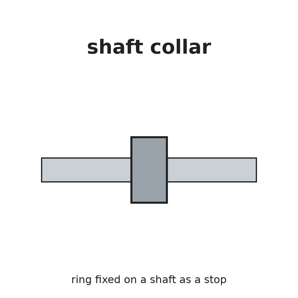
関連ブループリント
これらのブループリントは知識を共有しています — 技術、材料、原理
CC0 パブリックドメイン
このブループリントはCC0で公開されています。許可を求めずに、自由にコピー、修正、配布、あらゆる目的で使用できます。
メイカーを応援するには、ブループリント経由で製品を購入してください。メイカーには メイカーコミッション がベンダーにより設定されています。または、このブループリントの新しいイテレーションを作成し、自分のブループリントにコネクションとして含めて収益を共有できます。