アート
美容とウェルネス
工芸
文化と歴史
エンターテインメント
環境
食品と飲料
リバースエンジニアリング
科学
スポーツ
テクノロジー
ウェアラブル
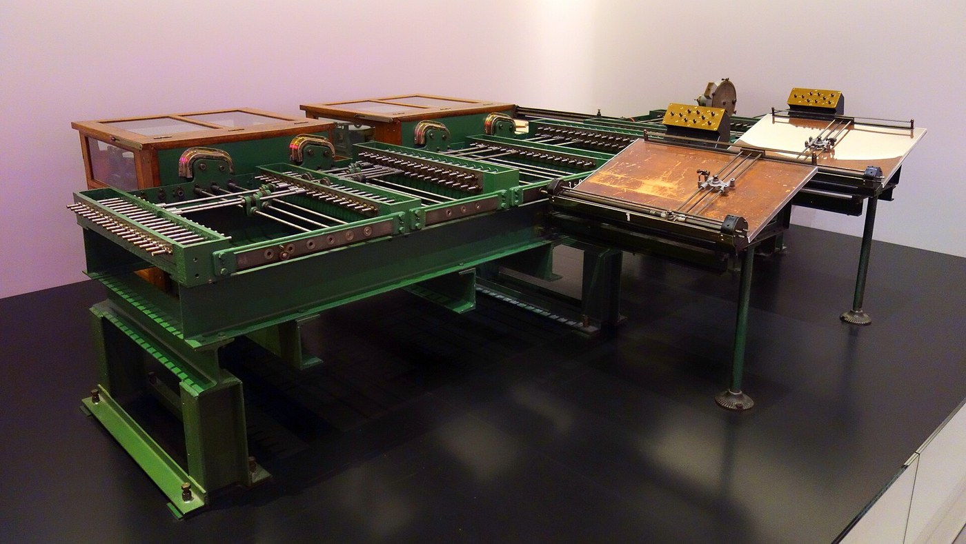


The Wheel-and-Disc Integrator
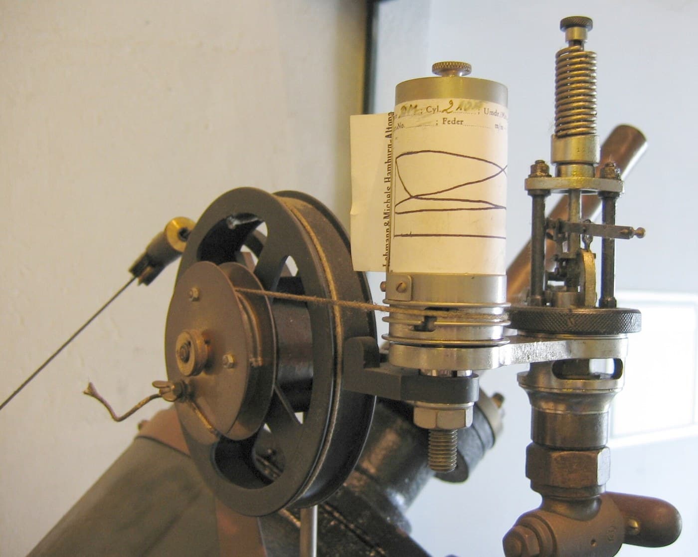
Stand a small friction wheel on a flat rotating disc with its axle pointing at the centre and its rim touching at radius x. Turn the disc once and the wheel is dragged along an arc of length two-pi-x, so it turns x over r times. Now move the wheel in and out while the disc keeps turning, and every increment of disc rotation adds whatever x happens to be at that instant. The wheel's total rotation is the integral of x, performed by friction, with no numbers anywhere.
William Thomson described this in 1876, together with a scheme for wiring several of them together to solve differential equations, and then could not build it. The reason is in the friction: a wheel pressed onto a disc with a few newtons can deliver perhaps twenty millinewton-metres before it slips, and setting the carriage of the NEXT integrator takes twenty times that. Each unit works; none of them can drive the next.
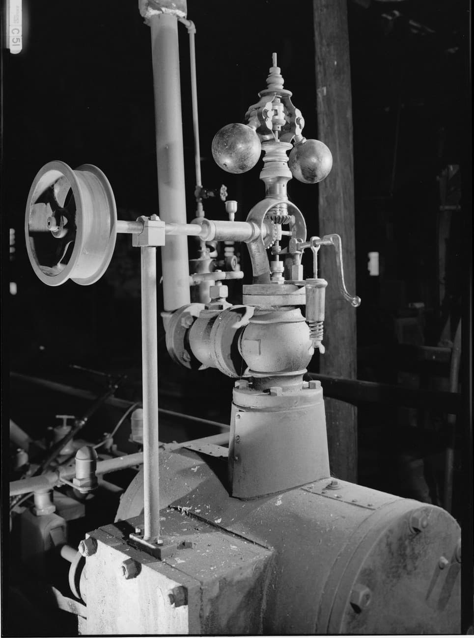
Vannevar Bush's differential analyser of 1931 solved it by putting a torque amplifier after every wheel. That is not a gearbox - gearing up the torque gears down the motion just as far, and the wheel has no motion to spare. It is a power amplifier: a band rides on a continuously driven capstan, the feeble wheel only has to tighten or slacken the band, and a separate motor does the work. Gains of ten thousand, from a mechanism that is itself a feedback loop, built a year before anybody could analyse one.
The machine that resulted solved ballistics, power-network transients and atomic-physics problems to about a tenth of a per cent per integrator, which was better than anything else available and is exactly the number that later lost to electronics. The op-amp integrator two blueprints further on does the same calculus by putting charge on a capacitor, and it wins because charge does not slip.
中級者
4 hours
手順
1
1
A disc, a wheel, and a carriage
A disc, a wheel, and a carriage
Cut a 300 mm plywood disc, true it on the drill, and drive it slowly from the geared motor. Face it with paper for grip.
Make the wheel from an O-ring on a 30 mm hub, on a shaft carried in two bearings, and mount the whole shaft on a carriage that slides along a rail across the disc's radius. Mark the rail in millimetres from the centre.
このステップの材料:
 合板1 枚
合板1 枚 O リングセット1 キット
 ボールベアリング2 個
 軟鋼丸棒300 mm
必要な工具:
 コードレスドリル
 ギヤードDCモーター
 デジタルノギス 6インチ
 定規
定規 直流安定化電源
2
2
Integrate something, then find the slip
Integrate something, then find the slip
Park the wheel at a fixed radius, count ten disc revolutions and count the wheel revolutions. The ratio should be the radius ratio; the shortfall is your slip.
Now do a real integral: crank the disc steadily and push the carriage out at a constant rate, so x rises linearly. The wheel should turn as t squared. Read it off at four times and plot against the arithmetic.
このステップの材料:
 方眼紙4 枚
必要な工具:
 ストップウォッチ定規
 鉛筆セット(黒鉛)
 デジタル回転計
3
3
The kinematics, the torque that is missing, and four integrators
The kinematics, the torque that is missing, and four integrators
Jupyter ノートブックを読み込み中…
必要な工具:
 デスクトップパソコン
4
4
Compendium: how a whole equation gets wired up
Compendium: how a whole equation gets wired up
The integrator is one unit; the analyser is what you make of six. Every variable in the problem is the angle of a shaft, and the machine is programmed by physically connecting shafts. To solve y-double-prime equals minus y you take a shaft carrying y, feed it to an integrator to get y-prime, feed that to a second to get y, and then couple the second output back to the first input through a reversing gear - a mechanical loop that literally is the differential equation. Addition is a differential gear; multiplying by a constant is a gear ratio; an arbitrary function is a shaped cam or a girl following a curve with a pointer while a servo copies her hand. Setting up one problem took a day or two, and changing a coefficient meant changing a gear.
It is worth knowing why the machines were kept long after electronic computers arrived. An analyser makes an error of a tenth of a per cent per integrator and never blows up, because friction is a physically bounded thing; early numerical integration on a digital machine could be far more accurate or catastrophically wrong depending on the step size, and nothing on the panel told you which. Operators who had watched a shaft turn could see the answer being wrong. That is a real advantage of an analogue machine and it is why the last differential analysers were still running into the 1950s.
材料
5- 1 枚プレースホルダー
- 1 キットプレースホルダー
- プレースホルダー
- 300 mmプレースホルダー
- 4 枚プレースホルダー
関連ブループリント
これらのブループリントは知識を共有しています — 技術、材料、原理


CC0 パブリックドメイン
このブループリントはCC0で公開されています。許可を求めずに、自由にコピー、修正、配布、あらゆる目的で使用できます。
メイカーを応援するには、ブループリント経由で製品を購入してください。メイカーには メイカーコミッション がベンダーにより設定されています。または、このブループリントの新しいイテレーションを作成し、自分のブループリントにコネクションとして含めて収益を共有できます。