Ushirikiano
SANAA
UREMBO NA USTAWI
UJANJA
UTAMADUNI NA HISTORIA
BURUDANI
MAZINGIRA
CHAKULA NA VINYWAJI
UHANDISI WA KINYUME
SAYANSI
MICHEZO
TEKNOLOJIA
VAZI
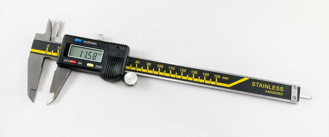


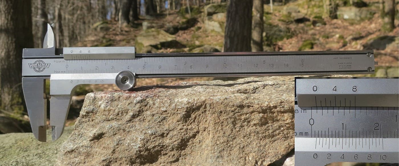
Digital Caliper: Capacitive Scale and Slider with Two-Chip Electronics (Baxter and Buehler, Starrett, 1986)
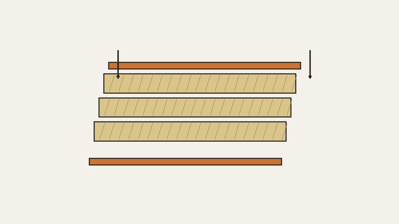
A six-inch caliper that reads out on a display. Under the slide, a strip of etched copper bars runs along the beam. Electrodes on the slider pass a signal through the bars by capacitance, and the slider's electronics count the bars crossed and work out the position in between.
Result: a digital caliper reading in inches or millimetres, repeatable to a ten-thousandth of an inch, with floating zero, peak hold and high/low limits. It runs on two 1.5 V cells at 10-50 microamps.
Source: L. K. Baxter and R. J. Buehler (L. S. Starrett Co.), US Patent 4,586,260 (1986). Unknown: the metal of the beam, slide and rod, their dimensions, the processor's program, and how the chips and display are made. Ours: the etchant, photoresist and glue. Picture: Wikimedia Commons.
Juu
2 days
Maagizo
1
1
Etch the scale
Etch the scale
Etch the scale pattern onto a strip of copper-clad epoxy fibreglass with photoresist and etchant. Each copper bar is 0.40 inch long, with a wider centre 0.12 inch long and two ends 0.14 inch long. Space the bars on 0.05 inch centres: the centres sit 0.004 inch apart, the ends 0.025 inch apart. Run the pattern the full length of the scale. Ours: dry film resist and ferric chloride.
Vifaa kwa hatua hii:
 Bamba tupu la mzunguko (lililofunikwa shaba)1 strip, length of the beam
Zana zinazohitajika:
 Filamu kavu ya kupinga mwanga
 Myeyusho wa kloridi ya feriki
 Glavu zinazostahimili kemikali
2
2
Fix the scale into the beam
Fix the scale into the beam
The beam is a metal bar with the fixed outside and inside jaws at one end, a wide shallow channel in its face and a second channel along its back. Fix the scale permanently into the face channel, copper up. The patent allows etching before or after this step. Not given: the metal, the dimensions and how the scale is fixed. Ours: epoxy.
Vifaa kwa hatua hii:
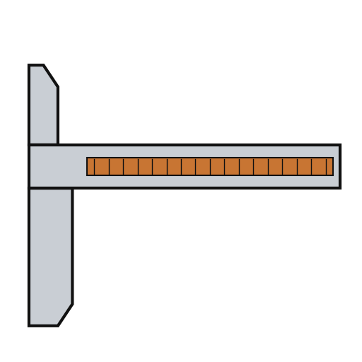 Upau wa kalipa1 with integral jaws
 Epoksi ya Sehemu Mbili1 a little
Zana zinazohitajika:
 Vipimo visivyojulikana
3
3
Fit the parts to the circuit
Fit the parts to the circuit
The circuit is one folded piece: a double-sided slider board joined by a flexible hinge to a circuit board. Its bottom face has two pickup electrodes, 0.750 x 0.110 inch and 0.0625 inch apart. On each side of them is an interdigitated transmitter array: fingers 0.115 inch long on 0.025 inch spacing, opening to 0.0375 inch at the centre. On the circuit board, solder or wire-bond the two chips: an NEC uPD7503 3 V processor (768 bits RAM, 2 kB ROM) and a CMOS gate array. Then fit the LCD, the 100 kHz crystal, the integrating capacitor and the MODE and SET buttons. Not given: the processor's program. Ours: a capacitor from a kit.
Vifaa kwa hatua hii:
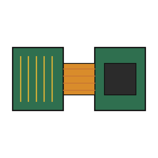 Bodi ya saketi gumu-nyumbufu1 slider board + circuit board
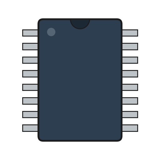 Saketi iliyounganishwa2 uPD7503 CPU, CMOS gate array
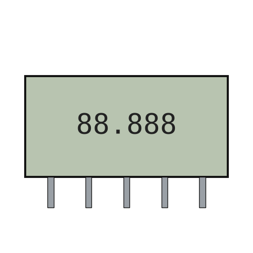 Paneli ya LCD ya sehemu1 5 digits
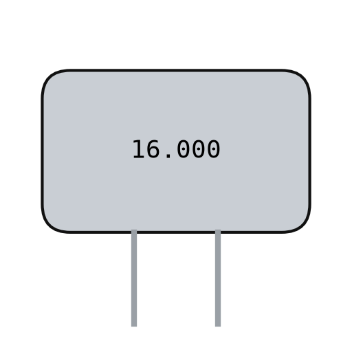 Kioo cha kwatsi1 100 kHz
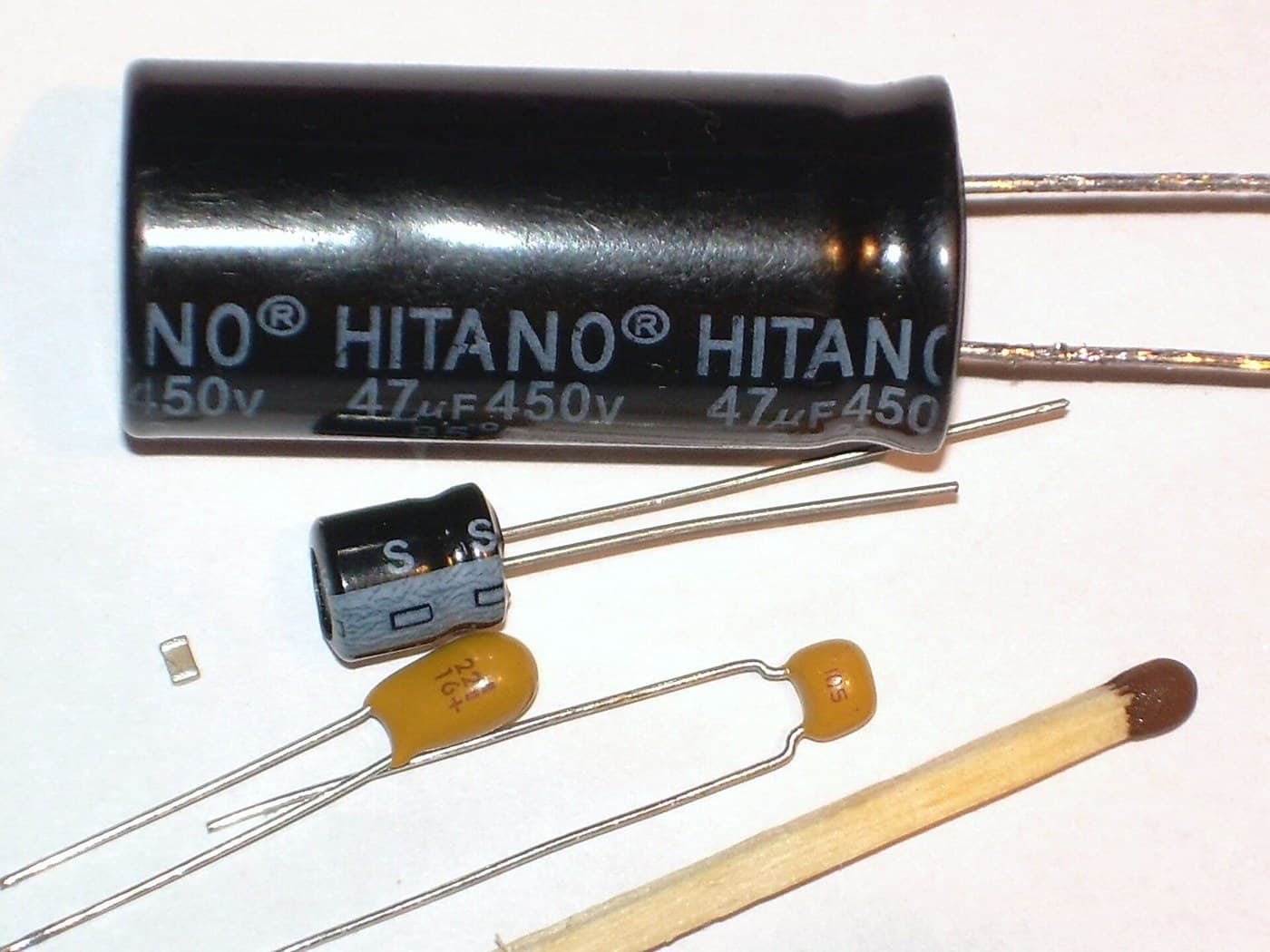
 Seti ya Kapasita1 one integrating capacitor
 Kitufe cha kubonyeza2 MODE, SET
 Waya wa Lehemu1 a little
Zana zinazohitajika:
 Chuma cha kulehemia
4
4
Build the slide
Build the slide
The slide frame wraps the back and edges of the beam and carries the movable jaws. Fix it to the depth rod, which runs in the back channel of the beam; the rod's free end is the depth gauge. Put the moulded plastic housing between the frame ends. Fasten two metal wear strips under the slider board, one on each side of the scale. They ride on the beam and connect the board's copper to it. Not given: the metal and sizes.
Vifaa kwa hatua hii:
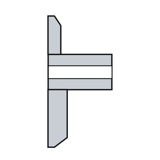 Fremu ya kitelezi1 with jaws
 Metali isiyojulikana1 depth rod and two wear strips
 Kasha la kitelezi1 kipande
Zana zinazohitajika:
Vipimo visivyojulikana Seti ya bisibisi sahihi
5
5
Assemble and check
Assemble and check
Fold the circuit into the housing recess, slider board facing the scale, and screw it to the frame. The electrodes must lie parallel to the scale bars at every point of travel. Put the two 1.5 V cells (the patent says 'zinc oxide') in the battery pockets of the circuit. The display shows five digits, a ten-thousandths bar graph, a minus sign and 'mm', plus PEAK, LOW, HIGH and LIMIT. Ours: check the reading against a vernier caliper.
Vifaa kwa hatua hii:
 Skrubu za mashine2 vipande
 Betri ya kifungo ya volti 1.52 vipande
Zana zinazohitajika:
Seti ya bisibisi sahihi Kalipa ya Vernier
Vifaa
15- 1 strip, length of the beamKishikilia Nafasi
- 1 with integral jawsKishikilia Nafasi
- 1 a littleKishikilia Nafasi
- 1 slider board + circuit boardKishikilia Nafasi
- 2 uPD7503 CPU, CMOS gate arrayKishikilia Nafasi
- 1 5 digitsKishikilia Nafasi
- 1 100 kHzKishikilia Nafasi
- 1 one integrating capacitorKishikilia Nafasi
- Kishikilia Nafasi
- 1 a littleKishikilia Nafasi
- 1 with jawsKishikilia Nafasi
- 1 depth rod and two wear stripsKishikilia Nafasi
- 1 kipandeKishikilia Nafasi
- 2 vipandeKishikilia Nafasi
- 2 vipandeKishikilia Nafasi
Zana Zinazohitajika
7- Kishikilia Nafasi
- Kishikilia Nafasi
- Kishikilia Nafasi
- Kishikilia Nafasi
- 2 vendors sell this, none ship to you yetKishikilia Nafasi
- Kishikilia Nafasi
- Kishikilia Nafasi
Vifaa vya Michoro Iliyounganishwa

Mchoro huu unatengeneza

Blueprint zinazohusiana
Blueprint hizi zinashiriki maarifa — mbinu, vifaa au kanuni
CC0 Umma Wote
Mchoro huu umetolewa chini ya CC0. Uko huru kunakili, kubadilisha, kusambaza, na kutumia kazi hii kwa madhumuni yoyote, bila kuomba ruhusa.
Saidia Mtengenezaji kwa kununua bidhaa kupitia Mchoro wao ambapo wanapata Kamisheni ya Mtengenezaji iliyowekwa na Wachuuzi, au unda marudio mapya ya Mchoro huu na uiunganishe kama kiungo katika Mchoro wako kuchangia mapato.