Ushirikiano
SANAA
UREMBO NA USTAWI
UJANJA
UTAMADUNI NA HISTORIA
BURUDANI
MAZINGIRA
CHAKULA NA VINYWAJI
UHANDISI WA KINYUME
SAYANSI
MICHEZO
TEKNOLOJIA
VAZI

Pocket Morse Code Learning Board - v.1
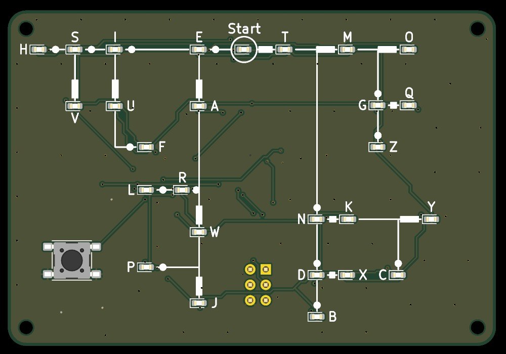
A pocket board, 80 x 55 mm, that teaches you to read Morse code. Its front is Dave Nathanson's Morse decoding chart: from Start, dots run one way and dashes the other, and every letter sits where its dots and dashes lead. Here every letter has its own LED. Press the key short for a dot and long for a dash, and the LED of the letter you have reached lights; pause, and it blinks.
It runs on one CR2032 coin cell and sleeps between uses. The board was drawn with Youblob's Draw PCB, and its checks pass, but it has not been built yet.
Juu
About 1 day, plus board delivery
Maagizo
1
1
LED current and keying speed
LED current and keying speed
Inapakia daftari la Jupyter…
2
2
The code it decodes
The code it decodes
This board reads the International Morse code letters as ITU-R M.1677-1 gives them.
3
3
Read the chart
Read the chart
Dave Nathanson (KG6ZJO) drew his decoding chart in 2010: "Start with your finger at "Start Here". Then move your finger to track the Morse dots & dashes. You will arrive at the correct letter!" On this board the LEDs do the tracking. ITU-R M.1677-1: "A dash is equal to three dots."
4
4
The schematic
The schematic
ATmega328P on its internal 8 MHz clock, straight from the coin cell; 27 LEDs charlieplexed on PC0-PC5 through six 330 Ω resistors; the key on INT0; a 2x3 ISP footprint.
Inapakia kitazamaji cha KiCanvas...
Kitazamaji cha Kitaalamu cha Usanifu wa PCB
5
5
The board
The board
Two layers, 80 x 55 mm. The chart, LEDs and key on the front; the chip, resistors, capacitors and cell holder on the back.
Inapakia kitazamaji cha KiCanvas...
Kitazamaji cha Kitaalamu cha Usanifu wa PCB
6
6
Order the board
Order the board
Open the board in KiCad and plot Gerber and drill files (File > Fabrication Outputs). Order a two-layer board, 1.6 mm thick, from any board maker that takes Gerbers.
Vifaa kwa hatua hii:
 Bamba la mzunguko lililochapishwa1 kipande
Zana zinazohitajika:
 Kompyuta yenye IDE ya Arduino
7
7
Solder the parts
Solder the parts
Back first: paste and reflow U1, R1-R7, C1-C3 and the cell holder BT1 with hot air. Then the front: the 27 red LEDs D1-D27 with pad 1 (cathode) as the board's assembly drawing shows, and the key SW1. Leave J1 empty. Clean off the flux, then test each LED's direction with the meter's diode test.
Vifaa kwa hatua hii:
 Kidhibiti-ndogo ATmega328P1 kipande
 LED ya chipu27 vipande
 Kipingamizi cha chipu7 vipande
 Kapasita ya kauri ya chipu3 vipande
 Kitufe cha kubonyeza1 kipande
 Kishikilia betri1 kipande
 Kibandiko cha kulehemu (kisicho na risasi)1 kipande
 Waya wa Lehemu1 kipande
Zana zinazohitajika:
 Kituo cha kurekebisha kwa hewa moto
 Chuma cha kulehemia
 Kibano chenye ncha nyembamba
 Fluksi
 Kioo cha Kukuza
 Kipima-umeme cha aina nyingi
 Alkoholi ya Isopropili 99%
8
8
The firmware
The firmware
pocket_morse_decoder_az.ino: every timing is a named constant at the top of the sketch. Board in the Arduino IDE: Arduino Pro or Pro Mini, ATmega328P (3.3V, 8 MHz).
pocket_morse_decoder_az.inoarduino
9
9
Set the fuses and upload
Set the fuses and upload
Do not use Burn Bootloader: the Pro board setting expects a crystal, and this board has none. Hold an ISP programmer's 2x3 pins on J1 and set the internal 8 MHz clock: avrdude -c usbasp -p m328p -U lfuse:w:0xE2:m -U hfuse:w:0xD9:m -U efuse:w:0xFF:m. Then, in the Arduino IDE, use Sketch > Upload Using Programmer.
Zana zinazohitajika:
 Kiprogramu cha AVR ISPKompyuta yenye IDE ya Arduino
10
10
Print the back shell
Print the back shell
An open-front shell, 84.8 x 59.8 x 8.9 mm, with four standoffs for M2 screws, a slot to slide the cell out and a window under J1. PLA, 0.2 mm layers, 20 % infill, printed on its floor.
11
11
Fit the shell
Fit the shell
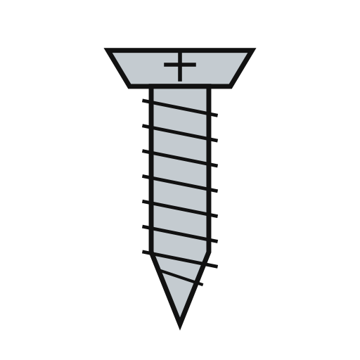
The shell leaves 5.0 mm for the back parts: measure your cell holder with a cell in it before you print. Check the holder's open side faces the board's left edge, where the shell's cell slot is. Slide in a CR2032 and screw the board into the shell with four M2 self-tapping screws.
Vifaa kwa hatua hii:
 Uzi wa PLA1 kipande
 Skrubu ya kujikatia hesi4 vipande
 Betri ya sarafu CR20321 kipande
Zana zinazohitajika:
 Printa ya 3D ya nyuzi (FDM)
 Kalipa ya Vernier
 Seti ya bisibisi sahihi
12
12
Troubleshooting
Troubleshooting
Pocket Morse decoder troubleshooting.
Flow
Loading...
13
13
History and honest limits
History and honest limits
The chart is **Dave Nathanson**'s (KG6ZJO), drawn in 2010 and shared as copyleft; his post says it is a novel way to decode by following a path. The letter codes are ITU-R M.1677-1's. The board, sizes, parts and timings are ours, drawn with Youblob's Draw PCB: its ERC and DRC pass with no errors and every LED's wiring was checked against the firmware by script, but it has not been built, flashed or tested.
Vifaa
12- 1 kipandeKishikilia Nafasi
- 1 kipandeKishikilia Nafasi
- 27 vipandeKishikilia Nafasi
- 7 vipandeKishikilia Nafasi
- 3 vipandeKishikilia Nafasi
- Kishikilia Nafasi
- Kishikilia Nafasi
- Kishikilia Nafasi
- 1 kipandeKishikilia Nafasi
- 1 kipandeKishikilia Nafasi
- 4 vipandeKishikilia Nafasi
- 1 kipandeKishikilia Nafasi
Zana Zinazohitajika
12- Kishikilia Nafasi
- Kishikilia Nafasi
- 2 vendors sell this, none ship to you yetKishikilia Nafasi
- Kishikilia Nafasi
- Kishikilia Nafasi
- Kishikilia Nafasi
- Kishikilia Nafasi
- Kishikilia Nafasi
- Kishikilia Nafasi
- Kishikilia Nafasi
- Kishikilia Nafasi
- Kishikilia Nafasi
Faili za muundo
1Mchoro huu unatengeneza

Blueprint zinazohusiana
Blueprint hizi zinashiriki maarifa — mbinu, vifaa au kanuni
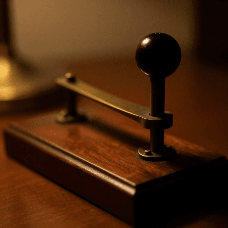

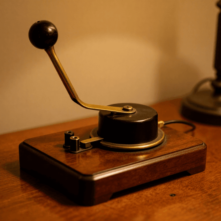
CC0 Umma Wote
Mchoro huu umetolewa chini ya CC0. Uko huru kunakili, kubadilisha, kusambaza, na kutumia kazi hii kwa madhumuni yoyote, bila kuomba ruhusa.
Saidia Mtengenezaji kwa kununua bidhaa kupitia Mchoro wao ambapo wanapata Kamisheni ya Mtengenezaji iliyowekwa na Wachuuzi, au unda marudio mapya ya Mchoro huu na uiunganishe kama kiungo katika Mchoro wako kuchangia mapato.