Ushirikiano
SANAA
UREMBO NA USTAWI
UJANJA
UTAMADUNI NA HISTORIA
BURUDANI
MAZINGIRA
CHAKULA NA VINYWAJI
UHANDISI WA KINYUME
SAYANSI
MICHEZO
TEKNOLOJIA
VAZI
Pocket Morse Code Learning Board - v.2
Admiral OOM

Imeundwa na

Admiral OOM

10. Novemba 2026NO
5
0
0
0
0

Pocket Morse Code Learning Board - v.2

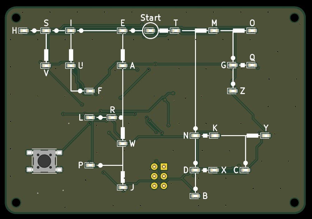
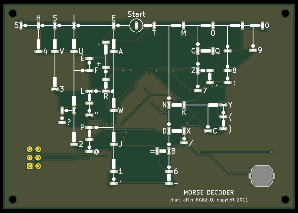
The complete pocket Morse decoder, 88 x 62 mm: every letter, the figures 0-9, the thirteen punctuation signs of the international code and the accented E, each with its own LED on Dave Nathanson's decoding chart. Press the key short for a dot and long for a dash, and the LED of the character you have reached lights; pause, and it blinks. It runs on one CR2032 coin cell and sleeps between uses. The board was drawn with Youblob's Draw PCB, and its checks pass, but it has not been built yet.
Juu
About 1 day, plus board delivery

Maagizo

1

LED current and keying speed

Inapakia daftari la Jupyter…
2

The letters-only board, before it

The same design with 27 LEDs. This one adds the figures and the signs, 59 LEDs in all.
3

Read the chart

Dave Nathanson's (KG6ZJO) complete chart adds the figures to his letters: "A-Z and Numbers (I left off the punctuation & symbols for simplicity)". This board adds them back from ITU-R M.1677-1 on new branches: . , : ? ' - / ( ) " = + @ and the accented E. Eight unlabelled LEDs are waypoints on the way to a figure or sign.
4

The schematic

ATmega328P on its internal 8 MHz clock, straight from the coin cell; 59 LEDs charlieplexed on nine lines (PC0-PC5, PD0, PD1, PD3) through 300 Ω resistors; the key on INT0; a 2x3 ISP footprint.

Inapakia kitazamaji cha KiCanvas...

Kitazamaji cha Kitaalamu cha Usanifu wa PCB

5

The board

Two layers, 88 x 62 mm. The chart, LEDs and key on the front; the chip, resistors, capacitors and cell holder on the back.

Inapakia kitazamaji cha KiCanvas...

Kitazamaji cha Kitaalamu cha Usanifu wa PCB

6

Order the board

Open the board in KiCad and plot Gerber and drill files (File > Fabrication Outputs). Order a two-layer board, 1.6 mm thick, from any board maker that takes Gerbers.

Vifaa kwa hatua hii:

Bamba la mzunguko lililochapishwaBamba la mzunguko lililochapishwa1 kipande

Zana zinazohitajika:

Kompyuta yenye IDE ya ArduinoKompyuta yenye IDE ya Arduino
7

Solder the parts

Back first: paste and reflow U1, R1-R10, C1-C3 and the cell holder BT1 with hot air. Then the front: the 59 red LEDs D1-D59 with pad 1 (cathode) as the board's assembly drawing shows, and the key SW1, a two-pad 6 x 6 mm switch to match its footprint. J1 is optional. Clean off the flux, then test each LED's direction with the meter's diode test.

Vifaa kwa hatua hii:

Kidhibiti-ndogo ATmega328PKidhibiti-ndogo ATmega328P1 kipande
LED ya chipuLED ya chipu59 vipande
Kipingamizi cha chipuKipingamizi cha chipu10 vipande
Kapasita ya kauri ya chipuKapasita ya kauri ya chipu3 vipande
Kitufe cha kubonyezaKitufe cha kubonyeza1 kipande
Kishikilia betriKishikilia betri1 kipande
Kibandiko cha kulehemu (kisicho na risasi)Kibandiko cha kulehemu (kisicho na risasi)1 kipande

Waya wa LehemuWaya wa Lehemu1 kipande

Zana zinazohitajika:

Kituo cha kurekebisha kwa hewa motoKituo cha kurekebisha kwa hewa moto
Chuma cha kulehemiaChuma cha kulehemia
Kibano chenye ncha nyembambaKibano chenye ncha nyembamba
FluksiFluksi
Kioo cha KukuzaKioo cha Kukuza
Kipima-umeme cha aina nyingiKipima-umeme cha aina nyingi
Alkoholi ya Isopropili 99%Alkoholi ya Isopropili 99%
8

The firmware

pocket_morse_decoder_complete.ino: every timing is a named constant at the top of the sketch. Board in the Arduino IDE: Arduino Pro or Pro Mini, ATmega328P (3.3V, 8 MHz).
pocket_morse_decoder_complete.inoarduino
/*
  Pocket Morse decoder - firmware for ATmega328P-AU, internal 8 MHz, CR2032 (3 V)
  Board: Arduino Pro or Pro Mini, ATmega328P (3.3V, 8 MHz)  (fqbn arduino:avr:pro:cpu=8MHzatmega328)
  Fuses for the internal 8 MHz RC oscillator (set once with an ISP programmer):
    lfuse 0xE2, hfuse 0xD9, efuse 0xFF (brown-out detector off to save the coin cell)
  Upload with "Upload Using Programmer" over the 2x3 ISP header.

  59 LEDs are charlieplexed on 9 pins (each pin through its own 300 ohm resistor).
  Only one LED is ever lit.  Button on INT0 (D2) to GND, internal pull-up.
*/
#include <avr/sleep.h>
#include <avr/power.h>
#include <avr/pgmspace.h>

// ---------------- timings (milliseconds) ----------------
const unsigned long DASH_THRESHOLD_MS = 250;    // press shorter = dot, longer (or equal) = dash
const unsigned long CHAR_GAP_MS       = 700;    // no press for this long ends the character
const unsigned long IDLE_SLEEP_MS     = 30000;  // no press for this long -> all off, power-down sleep
const unsigned long BLINK_ON_MS       = 150;    // result blink: LED on time
const unsigned long BLINK_OFF_MS      = 150;    // result blink: LED off time
const uint8_t       BLINK_COUNT       = 3;      // number of result blinks
const unsigned long DEBOUNCE_MS       = 20;     // button debounce time

// ---------------- hardware ----------------
const uint8_t BUTTON_PIN = 2;                   // PD2 / INT0
// charlieplex lines L1..L9 -> PC0..PC5, PD0, PD1, PD3
const uint8_t LINE_PIN[9] = {A0, A1, A2, A3, A4, A5, 0, 1, 3};
const uint8_t MAX_CODE_LEN = 7;

struct Node { uint8_t len; uint8_t bits; uint8_t anode; uint8_t cathode; };
// bits: symbol j of the code is bit j (1 = dash). Index 0 is Start.
const Node NODES[] PROGMEM = {
  {0, 0x00, 0, 8},  // D1 S Start
  {1, 0x01, 3, 8},  // D2 - T
  {1, 0x00, 8, 0},  // D3 . E
  {2, 0x03, 3, 6},  // D4 -- M
  {2, 0x01, 6, 5},  // D5 -. N
  {2, 0x02, 0, 3},  // D6 .- A
  {2, 0x00, 8, 1},  // D7 .. I
  {3, 0x07, 3, 7},  // D8 --- O
  {3, 0x03, 6, 7},  // D9 --. G
  {3, 0x05, 5, 6},  // D10 -.- K
  {3, 0x01, 5, 2},  // D11 -.. D
  {3, 0x06, 4, 1},  // D12 .-- W
  {3, 0x02, 1, 7},  // D13 .-. R
  {3, 0x04, 1, 3},  // D14 ..- U
  {3, 0x00, 8, 3},  // D15 ... S
  {4, 0x0F, 3, 5},  // D16 ---- _
  {4, 0x07, 5, 7},  // D17 ---. _
  {4, 0x0B, 7, 6},  // D18 --.- Q
  {4, 0x03, 7, 8},  // D19 --.. Z
  {4, 0x0D, 8, 2},  // D20 -.-- Y
  {4, 0x05, 6, 2},  // D21 -.-. C
  {4, 0x09, 6, 0},  // D22 -..- X
  {4, 0x01, 2, 5},  // D23 -... B
  {4, 0x0E, 0, 1},  // D24 .--- J
  {4, 0x06, 2, 4},  // D25 .--. P
  {4, 0x0A, 1, 2},  // D26 .-.- _
  {4, 0x02, 7, 1},  // D27 .-.. L
  {4, 0x0C, 7, 2},  // D28 ..-- _
  {4, 0x04, 2, 1},  // D29 ..-. F
  {4, 0x08, 3, 4},  // D30 ...- V
  {4, 0x00, 8, 4},  // D31 .... H
  {5, 0x1F, 5, 3},  // D32 ----- 0
  {5, 0x0F, 7, 5},  // D33 ----. 9
  {5, 0x07, 8, 7},  // D34 ---.. 8
  {5, 0x13, 6, 8},  // D35 --..- _
  {5, 0x03, 8, 6},  // D36 --... 7
  {5, 0x0D, 2, 8},  // D37 -.--. (
  {5, 0x09, 0, 6},  // D38 -..-. /
  {5, 0x11, 0, 2},  // D39 -...- =
  {5, 0x01, 5, 0},  // D40 -.... 6
  {5, 0x1E, 1, 5},  // D41 .---- 1
  {5, 0x16, 0, 4},  // D42 .--.- _
  {5, 0x0A, 3, 2},  // D43 .-.-. +
  {5, 0x12, 2, 7},  // D44 .-..- _
  {5, 0x1C, 4, 0},  // D45 ..--- 2
  {5, 0x0C, 7, 4},  // D46 ..--. _
  {5, 0x04, 3, 1},  // D47 ..-.. É
  {5, 0x18, 1, 4},  // D48 ...-- 3
  {5, 0x10, 4, 3},  // D49 ....- 4
  {5, 0x00, 4, 8},  // D50 ..... 5
  {6, 0x07, 8, 5},  // D51 ---... :
  {6, 0x33, 5, 8},  // D52 --..-- ,
  {6, 0x2D, 2, 6},  // D53 -.--.- )
  {6, 0x21, 0, 5},  // D54 -....- -
  {6, 0x1E, 5, 1},  // D55 .----. '
  {6, 0x16, 2, 0},  // D56 .--.-. @
  {6, 0x2A, 3, 0},  // D57 .-.-.- .
  {6, 0x12, 4, 2},  // D58 .-..-. "
  {6, 0x0C, 4, 7},  // D59 ..--.. ?
};
const uint8_t NODE_COUNT = sizeof(NODES) / sizeof(NODES[0]);
const uint8_t START_NODE = 0;
const int8_t  NO_NODE = -1;

volatile bool wokeUp = false;

void allOff() {
  for (uint8_t i = 0; i < 9; i++) {
    pinMode(LINE_PIN[i], INPUT);
    digitalWrite(LINE_PIN[i], LOW);
  }
}

void lightNode(int8_t idx) {
  allOff();
  if (idx < 0 || idx >= NODE_COUNT) return;
  uint8_t a = pgm_read_byte(&NODES[idx].anode);
  uint8_t k = pgm_read_byte(&NODES[idx].cathode);
  digitalWrite(LINE_PIN[k], LOW);
  pinMode(LINE_PIN[k], OUTPUT);
  digitalWrite(LINE_PIN[a], HIGH);
  pinMode(LINE_PIN[a], OUTPUT);
}

int8_t findNode(uint8_t len, uint8_t bits) {
  for (uint8_t i = 0; i < NODE_COUNT; i++) {
    if (pgm_read_byte(&NODES[i].len) == len && pgm_read_byte(&NODES[i].bits) == bits) return i;
  }
  return NO_NODE;
}

bool buttonDown() { return digitalRead(BUTTON_PIN) == LOW; }

// wait until the button state is stable; returns that state
bool debouncedState() {
  bool s = buttonDown();
  unsigned long t = millis();
  while (millis() - t < DEBOUNCE_MS) {
    if (buttonDown() != s) { s = buttonDown(); t = millis(); }
  }
  return s;
}

void blink(int8_t idx) {
  for (uint8_t i = 0; i < BLINK_COUNT; i++) {
    lightNode(idx); delay(BLINK_ON_MS);
    allOff();       delay(BLINK_OFF_MS);
  }
}

void wakeISR() {
  detachInterrupt(digitalPinToInterrupt(BUTTON_PIN));
  wokeUp = true;
}

void goToSleep() {
  allOff();
  while (debouncedState()) {}              // make sure the button is released
  uint8_t adcsra = ADCSRA;
  ADCSRA = 0;                               // ADC off
  set_sleep_mode(SLEEP_MODE_PWR_DOWN);
  noInterrupts();
  wokeUp = false;
  EIFR = bit(INTF0);
  attachInterrupt(digitalPinToInterrupt(BUTTON_PIN), wakeISR, LOW);  // level interrupt wakes from power-down
  sleep_enable();
  sleep_bod_disable();
  interrupts();
  sleep_cpu();
  sleep_disable();
  ADCSRA = adcsra;
  while (debouncedState()) {}              // the waking press only wakes the board
}

uint8_t codeLen = 0;
uint8_t codeBits = 0;
bool    codeValid = true;
unsigned long lastActivity = 0;

void resetToStart() {
  codeLen = 0; codeBits = 0; codeValid = true;
  lightNode(START_NODE);
}

void setup() {
  for (uint8_t p = 4; p <= 13; p++) pinMode(p, INPUT_PULLUP);  // unused pins: no floating inputs
  pinMode(BUTTON_PIN, INPUT_PULLUP);
  allOff();
  power_spi_disable();
  power_twi_disable();
  power_usart0_disable();
  resetToStart();
  lastActivity = millis();
}

void loop() {
  unsigned long now = millis();

  if (debouncedState()) {                    // button pressed
    unsigned long pressStart = millis();
    while (debouncedState()) {}
    unsigned long pressLen = millis() - pressStart;
    bool dash = pressLen >= DASH_THRESHOLD_MS;
    if (codeValid && codeLen < MAX_CODE_LEN) {
      if (dash) codeBits |= (1 << codeLen);
      codeLen++;
      int8_t n = findNode(codeLen, codeBits);
      if (n == NO_NODE) { codeValid = false; allOff(); }
      else lightNode(n);
    } else {
      codeValid = false; allOff();
    }
    lastActivity = millis();
    return;
  }

  if (codeLen > 0 && now - lastActivity >= CHAR_GAP_MS) {   // end of character
    if (codeValid) blink(findNode(codeLen, codeBits));
    else blink(START_NODE);
    resetToStart();
    lastActivity = millis();   // idle time counts from the end of the character
    return;
  }

  if (codeLen == 0 && now - lastActivity >= IDLE_SLEEP_MS) {
    goToSleep();
    resetToStart();            // on wake light Start
    lastActivity = millis();
  }
}
9

Set the fuses and upload

Do not use Burn Bootloader: the Pro board setting expects a crystal, and this board has none. Hold an ISP programmer's 2x3 pins on J1 and set the internal 8 MHz clock: avrdude -c usbasp -p m328p -U lfuse:w:0xE2:m -U hfuse:w:0xD9:m -U efuse:w:0xFF:m. Then, in the Arduino IDE, use Sketch > Upload Using Programmer.

Zana zinazohitajika:

Kiprogramu cha AVR ISPKiprogramu cha AVR ISP
Kompyuta yenye IDE ya ArduinoKompyuta yenye IDE ya Arduino
10

Print the back shell

An open-front tray, 92.6 x 66.6 x 8.3 mm, with four standoffs for M2 screws, a notch and floor opening to slide the cell out and an opening under J1. PLA, 0.2 mm layers, 20 % infill, printed on its floor.
Faili ya UsanifuSTLCC0 - Free
11

Fit the shell

The standoffs hold the board 6.7 mm above the floor: measure your cell holder with a cell in it before you print. Check the holder's open end faces the board's bottom edge, where the shell's cell notch is. Slide in a CR2032 and screw the board into the shell with four M2 x 8 self-tapping screws.

Vifaa kwa hatua hii:
Uzi wa PLAUzi wa PLA1 kipande
Skrubu ya kujikatia hesiSkrubu ya kujikatia hesi4 vipande
Betri ya sarafu CR2032Betri ya sarafu CR20321 kipande

Zana zinazohitajika:

Printa ya 3D ya nyuzi (FDM)Printa ya 3D ya nyuzi (FDM)
Kalipa ya VernierKalipa ya Vernier
Seti ya bisibisi sahihiSeti ya bisibisi sahihi
12

Troubleshooting

Pocket Morse decoder troubleshooting.

Flow

Loading...
13

History and honest limits

The letters and figures follow **Dave Nathanson**'s (KG6ZJO) complete chart of 2011, shared as copyleft. Where the signs sit is ours; their codes are ITU-R M.1677-1's. The board, sizes, parts and timings are ours, drawn with Youblob's Draw PCB: its ERC and DRC pass with no errors and every LED's wiring, code and label was checked against the firmware by script, but it has not been built, flashed or tested.

Vifaa

12

Zana Zinazohitajika

12

Faili za muundo

1

CC0 Umma Wote

Mchoro huu umetolewa chini ya CC0. Uko huru kunakili, kubadilisha, kusambaza, na kutumia kazi hii kwa madhumuni yoyote, bila kuomba ruhusa.

Saidia Mtengenezaji kwa kununua bidhaa kupitia Mchoro wao ambapo wanapata Kamisheni ya Mtengenezaji iliyowekwa na Wachuuzi, au unda marudio mapya ya Mchoro huu na uiunganishe kama kiungo katika Mchoro wako kuchangia mapato.

Majadiliano

(0)

Ingia kujiunga na majadiliano

Inapakia maoni...