Building a Heron's Automaton — A Self-Moving Theatrical Machine Powered by Falling Sand
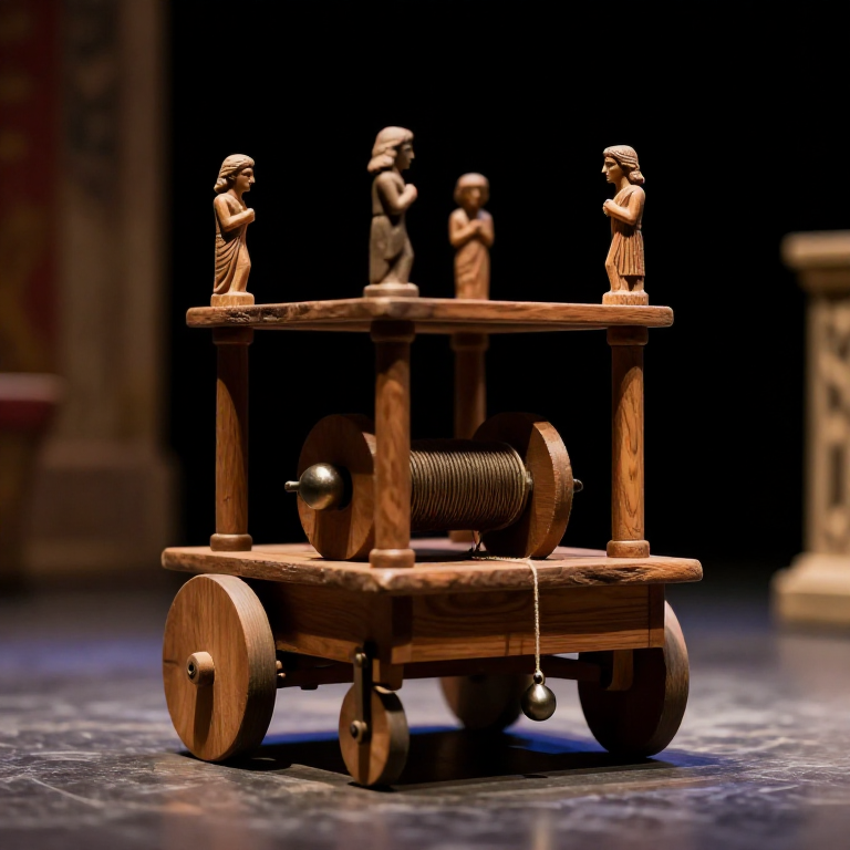
Hero of Alexandria described in his treatise 'Automata' (Αὐτοματοποιητική) a series of self-operating theatrical machines — robots, in the modern sense — capable of moving autonomously, performing sequences of actions, and stopping at predetermined points, all without human intervention during operation. The most remarkable described a wheeled platform on which a small dramatic scene was enacted: figures moved, turned, and performed actions corresponding to the mythological story of Nauplius and the Greeks returning from Troy, complete with a simulated sea voyage with waves (created by strings of wooden cylinders inside the stage), fire (a real flame raised at the correct moment), and dolphins jumping from the simulated sea.
The power source for these automata was elegant in its simplicity: a container of sand or lead shot placed on the stage, connected by a string wrapped around an axle. As the sand fell (or the lead was poured from one container to another), the string unwound from the axle, rotating it. By winding different strings around the same axle at different positions, different motions were triggered at different times during the sand-fall — the winding pattern was the program. Adding a string that first went around the axle clockwise and then counter-clockwise produced a motion that went forward and then back. Multiple strings on the same axle, connecting to different figures, produced independent coordinated motions. This is a genuine programming system: the physical arrangement of strings on the axle encodes a sequence of movements in a medium that any carpenter can read and modify.
Hero's automata represent arguably the most conceptually advanced engineering achievement of antiquity — not in the precision of their parts or the force of their actions, but in the abstraction they embody: the separation of the program (the string winding) from the execution (the falling sand motor). This is the same conceptual distinction that defines modern computing — program separate from hardware — implemented 1,700 years before Charles Babbage's Analytical Engine and 1,900 years before the electronic stored-program computer. The automata were theatrical devices, not practical machines, and so never drove technological development the way the water mill or the press did. But they demonstrate that the ancient mind had no barrier to the concept of programmed mechanical behaviour.
ការណែនាំ
Design the motion sequence — write the program first
Design the motion sequence — write the program first
Before building any physical component, write out the complete motion sequence as a timeline. This is the program — the winding pattern of the strings around the drive axle is determined entirely by this sequence. Example program for a simple automaton performing a 60-second sequence:
0–10 seconds: Platform moves forward 40 cm. 10–20 seconds: Platform stationary; Figure A (left side) rotates 90° clockwise. 20–30 seconds: Platform moves right 20 cm. 30–40 seconds: Figure A rotates back 90° counter-clockwise; Figure B (right side) raises arm 45°. 40–50 seconds: Platform moves forward 20 cm further. 50–60 seconds: Platform stationary; both figures return to start position.
Convert each action to required axle rotation. If the drive axle is 3 cm diameter (circumference = 9.4 cm), then 10 cm of sand-fall time pays out one string revolution = one axle turn = approximately 10 cm of string unwinding. For the platform to move 40 cm in step one, the wheel-drive string must unwind 40 cm of string on the drive axle — requiring 40 / 9.4 ≈ 4.3 axle revolutions. Calculate all string unwind lengths from the motion distances and durations, then verify they fit on the axle without overlap (strings from different motions wound at different axle positions must not touch each other).
Build the wheeled platform base
Build the wheeled platform base
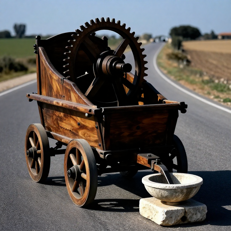
The platform is a flat wooden stage approximately 30 cm × 40 cm, on four wheels. Build it from 2 cm thick hardwood planks (oak or beech), with a sturdy frame and smooth plank decking. The four wheels must allow the platform to move in two directions: forward-backward and side-to-side. This is achieved with a directional wheel arrangement: the two front wheels are mounted on a turntable (swiveling axle) and the two rear wheels are mounted on a fixed axle. When the front axle is turned by the steering string, the platform curves in the direction of the turn. This is the same principle as a horse-drawn cart — front-wheel steering.
Make the wheels from hardwood discs approximately 8 cm diameter and 2 cm thick. The axle pins are iron or bronze rods approximately 5 mm diameter, press-fitted through the wheel centres (rotating freely) and fixed in bearing brackets below the platform edge. Keep the wheel pins well-lubricated with tallow — the platform must roll freely enough that the weight of the falling sand (typically 500 g–1 kg) can pull it across a smooth floor without the wheel friction stopping the motion. Test rolling resistance: the platform must roll across a level floor when pushed with less than 100 g of horizontal force.
Materials for this step:
 Hardwood Block3 piece
 Iron Nails30 piece
Tools needed:
 Hand Saw
 Awl
AwlBuild the sand motor and drive axle
Build the sand motor and drive axle
The sand motor is the power source. A sealed wooden box approximately 15 × 10 × 20 cm tall contains fine dry sand. A small hole in the bottom (2–3 mm diameter, adjustable with a sliding plate) allows sand to fall into a lower receptacle at a controlled rate. The rate of sand flow through a circular orifice in the bottom of a container follows Torricelli's theorem: the flow rate is approximately proportional to the square root of the sand head above the orifice. For consistent timing, the orifice must be small enough that the head variation (as sand level drops during operation) changes the flow rate by no more than 20% over the entire sequence duration.
The falling sand's weight drives the motor: a string tied to the upper sand container passes over a small pulley at the top of the machine, then connects to the drive axle. As sand falls from the upper to lower container, the upper container becomes lighter and the lower heavier — the weight difference creates a tension in the string that turns the axle. Alternatively, the sand container can simply be mounted on one side of a lever beam connected to the axle — as sand transfers from upper to lower, the lever tips and turns the axle. For a consistent, controllable motion, the direct string-over-pulley drive is superior to the lever arrangement.
Materials for this step:
Hardwood Block2 piece Hemp Cord5 meter
Make the drive axle and wind the programming strings
Make the drive axle and wind the programming strings
The drive axle is a wooden or bronze cylinder 3 cm in diameter and 20 cm long, mounted horizontally on two bearing brackets above the platform. All motion-controlling strings are wound around this single axle at different axial positions. The axle is the program storage medium: different strings wound at different positions unwind in sequence as the axle rotates, triggering their respective motions at the calculated times.
To wind the programming strings: refer to your motion-sequence timeline (from Step 1) and the calculated string lengths for each motion. Begin with the last motion in the sequence (it will be wound innermost on the axle). Wind the string for the last motion around the axle by the calculated number of turns (40 cm / 9.4 cm per turn ≈ 4.3 turns for a 40 cm motion). Tie off the end. Then wind the next-to-last motion's string adjacent on the axle, by its calculated turns. Continue toward the first motion, which ends up outermost. When the axle starts turning, the outermost string (first motion) unwinds first, then the next, and so on — the sequence runs in the correct order automatically.
Materials for this step:
Hardwood Block1 pieceHemp Cord15 meterBuild the steering mechanism for directional movement
Build the steering mechanism for directional movement
To steer the platform left and right while it moves forward, the front axle turntable must be connected to a steering string wound around the drive axle. When the string attached to the right side of the front axle turntable unwinds, the turntable rotates right and the platform curves right. When the left-side string unwinds, the platform curves left. By winding right-turn and left-turn string sections in sequence on the drive axle between forward-motion sections, arbitrary curved paths can be programmed.
The steering string passes from the drive axle, over guide pulleys mounted on the platform sides, to the front turntable axle. The string must have zero slack (no sag) when the turntable is centred — any slack means there is a 'dead band' at the start and end of each steering section where the axle turns but the turntable has not yet moved. Adjust string lengths by tying adjustable slip knots at the turntable attachment points. Test the steering mechanism manually by rotating the drive axle by hand through several turns and observing the platform tracking across the floor — it should trace the intended path accurately.
Materials for this step:
Hemp Cord5 meterBuild the automated figure(s) for the stage
Build the automated figure(s) for the stage
The figures are simple jointed wooden puppets mounted on posts on the platform. Each figure has at most 2–3 moving joints — a shoulder joint for arm raising, a neck joint for head turning, or a waist joint for bowing — controlled by their individual strings wound around the drive axle. Keep the figure geometry simple: a human figure approximately 15 cm tall with one or two hinge points. The hinge is a simple pin joint (iron wire through aligned holes in the body parts), with a return spring of bent bronze wire or twisted sinew that pulls the joint back to its rest position when the driving string relaxes.
String the figures so that each motion requires only one string direction: pulling the string raises an arm (spring returns it when string slackens); pulling a different string rotates the head (spring returns). This means each figure joint needs one programming string wound on the drive axle, plus a passive return spring on the joint. For a figure with two independent motions (arm raise + head turn), two string positions on the drive axle are consumed. The drive axle must be long enough to accommodate all figure-motion strings plus all steering strings without running out of axle length.
Materials for this step:
Hardwood Block2 pieceIron Nails15 pieceTools needed:
 Sharp Knife
Calibrate sand flow rate to timing requirements
Calibrate sand flow rate to timing requirements
The sand flow rate determines how fast the axle turns and thus how fast the sequence executes. Calibrate the orifice size so that the axle completes one full revolution in the desired number of seconds. For a 60-second total sequence and an axle circumference of 9.4 cm, calculate total string wound on axle: this equals the sum of all string section lengths from all motions. If total string length = 150 cm and axle circumference = 9.4 cm, total axle turns = 150 / 9.4 = 16 turns for 60 seconds, so desired axle speed = 16 / 60 = 0.267 turns per second = 16 RPM. Set the sand orifice size so that the sand falls at a rate that produces this axle speed under the actual string tension (which depends on figure weights, platform rolling resistance, and sand-container weight differential).
Calibration is empirical: measure actual sequence duration with the full automaton assembled and sand flowing. If the sequence runs too fast (under 60 seconds), reduce the orifice size by sliding the control plate partially over the hole. If too slow, enlarge the orifice slightly. Sand flow rate is sensitive to humidity — dry fine sand flows easily, while slightly damp sand forms arches over the orifice and stops flowing. Use only thoroughly dry fine sand (beach sand dried in sunlight for a day is ideal) and store the sand in a sealed container to prevent moisture absorption between uses.
Test the complete sequence — the first run
Test the complete sequence — the first run
Set the automaton on a smooth, level floor surface. Place the platform in its starting position. Open the sand orifice and step back — do not intervene. Watch the complete sequence execute. The key question is: does each motion start and stop at the correct moment? If a motion starts correctly but the figure over-rotates or the platform moves too far, the string section for that motion is too long — reduce by untying and re-winding with fewer turns. If the motion does not complete fully (arm only rises partway), the string is too short — add more turns.
On the first run, expect to make 5–10 corrections to the programming strings. This is normal — the calculation from string length to motion distance never accounts for all friction and slip in the system. The correction process is exactly equivalent to debugging a computer program: identify which step executes incorrectly, identify which string section controls that step, measure the error (over-travel or under-travel in centimetres), convert to axle turns to add or remove, and re-wind. Document each correction on the original motion-sequence timeline so the corrected program can be reproduced reliably on the next reset.
Reset the automaton for a second run
Reset the automaton for a second run
Resetting the automaton requires reversing all the operations that occurred during the run. Move the platform back to the start position (rolling it back by hand). Return all figures to their rest positions by rotating each joint back to its original angle. Re-wind all the programming strings back onto the drive axle, turning the axle counter-clockwise by the same number of turns it advanced during the run — return the fallen sand to the upper container. Check that each string is re-wound in the correct position (right string at its axle position, correct number of turns) before the next run.
The reset process reveals the programming system's physical nature: re-winding the strings is literally re-loading the program. If any string is re-wound at the wrong position on the axle, the sequence will execute incorrectly on the next run — the equivalent of a data corruption error. The reset procedure also verifies system integrity: if a string is too short to re-wind fully (cannot return the joint to full rest position), the string stretched during the previous run and must be replaced. Natural fibre strings (hemp) stretch slightly under sustained tension and must be replaced every 5–10 run cycles in a well-calibrated automaton.
Add additional programmed effects
Add additional programmed effects
Extend the automaton's capabilities by adding additional programmed effects beyond platform movement and figure motion. Hero's own description includes simulated fire (a small oil wick lamp raised at the correct moment by a lever connected to the drive axle), simulated waves (a string of wooden rollers driven by their own separate string section), and acoustic effects (small bells struck by wire levers connected to the program axle). Each additional effect requires only an additional string section on the drive axle and a mechanical linkage to the effect actuator.
A sound effect mechanism: mount a small bell on the platform with a striker arm connected to the drive axle by a short string. When the string section for the bell unwinds, the striker arm swings and hits the bell — a single, timed chime at a programmed moment in the sequence. To produce two chimes in sequence (ding-ding), wind two separate short string sections on the axle with a small gap between them (representing the silence between chimes). The gap allows the striker arm spring to reset between the two pulls. This multi-event timing from a single axle demonstrates that the programmed-effect concept is extensible without limit — the axle is the bus, strings are I/O lines, and the wound pattern is the program.
Materials for this step:
Hemp Cord5 meterThe philosophy of the first programmable machine
The philosophy of the first programmable machine
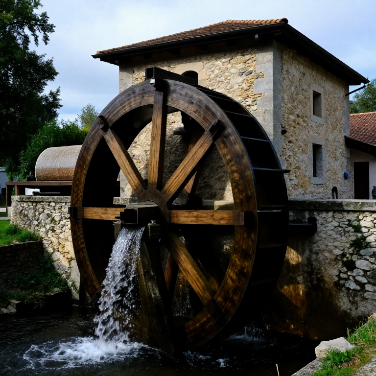
Hero's automaton crosses a conceptual threshold that separates it from all previous machines: it is programmable. A water wheel is not programmable — it turns at the speed the water dictates, in the direction the water pushes, continuously until the water stops. An aeolipile is not programmable — it spins in reaction to steam, at a speed determined by the steam pressure, with no sequence of actions. But the automaton performs a specific sequence of specific actions in a specific order and at specific times — and that sequence can be changed by changing the winding pattern of the strings without rebuilding the machine. This is the definition of programmability.
The stored program (string winding on axle) is analogous to the punched cards that controlled Jacquard looms in 1804, which directly inspired Charles Babbage's Analytical Engine concept (1837), which directly inspired the stored-program electronic computer (von Neumann architecture, 1945). The conceptual chain from Hero's wound strings to the CPU instruction stream is unbroken in its logical structure, even though it was historically discontinuous — each inventor rediscovered the concept of storing a sequence of instructions in a medium separate from the execution mechanism. Hero's contribution was to discover and demonstrate this concept first, in the only medium available to him: string and wood.
Scale up — Heron's complete theatrical automaton
Scale up — Heron's complete theatrical automaton
Hero's full description in 'Automata' includes a two-act theatrical performance ('An Offering to Nauplius') lasting several minutes, with scene changes, moving figures, simulated sea, fire effects, and the platform navigating a complex path — turning, stopping, returning, and stopping again. Replicating this fully requires a much longer drive axle (perhaps 60 cm or more) to accommodate all the motion strings, a more powerful motor (heavier sand or lead shot containers for greater torque), and more precise string calibration than the simple demonstrator described in this blueprint.
The scaling path is clear: increase axle length for more programming steps, increase motor weight for more torque (to overcome the greater friction from more strings and heavier figures), and use bronze or iron for the axle and bearings (reducing wear that would gradually alter timing on wooden axle surfaces). A full-scale Heronian theatrical automaton with 10 minutes of programmed performance and 6–8 independent actuators is a realistic project for a maker with 3–6 months of focused work. Building it will produce the same revelation that Hero apparently intended his device to provoke: that autonomous mechanical behaviour, appearing to observers as mysterious self-will, is in fact nothing more than physics following a path prepared in advance by the maker's hands.
សម្ភារៈ
3- 8 pieceកន្លែងទុក
- 45 pieceកន្លែងទុក
Connected Blueprint Materials
ប្លង់ពាក់ព័ន្ធ
ប្លង់ទាំងនេះចែករំលែកចំណេះដឹង — បច្ចេកទេស សម្ភារៈ ឬគោលការណ៍
Related blueprints
Other builds that share materials, tools, or techniques with this one.


CC0 សាធារណៈ
ប្លង់នេះត្រូវបានចេញផ្សាយក្រោម CC0។ អ្នកមានសិទ្ធិចម្លង កែប្រែ ចែកចាយ និងប្រើប្រាស់ដោយមិនចាំបាច់សុំអនុញ្ញាត។
គាំទ្រអ្នកបង្កើតដោយទិញផលិតផលតាមរយៈប្លង់របស់ពួកគេ ដែលពួកគេទទួលបាន កម្រៃជើងសារអ្នកបង្កើត កំណត់ដោយអ្នកលក់ ឬបង្កើតកំណែថ្មីនៃប្លង់នេះ ហើយបញ្ចូលជាការតភ្ជាប់ក្នុងប្លង់របស់អ្នកដើម្បីចែករំលែកចំណូល។