

Scaffolding and the Putlog
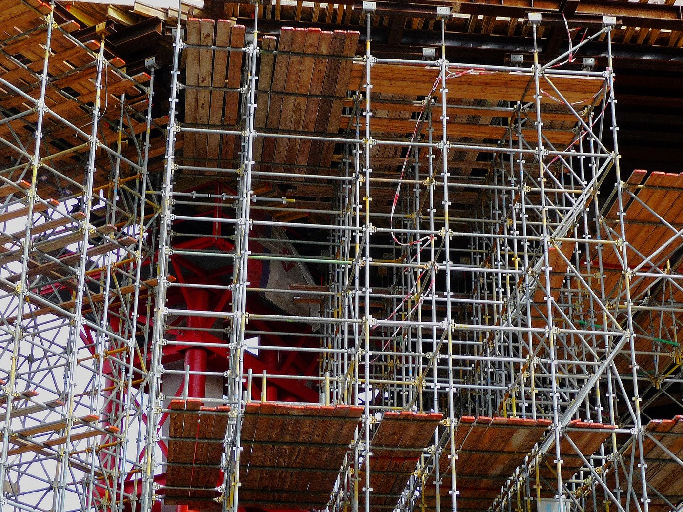
A scaffold is a building you throw away. It carries people, tools and material up the face of a permanent structure, holds them there while the structure is built, and then comes down. Nothing about it survives — which is exactly why almost nobody thinks about how it works.
It works by being a complete load path to the ground. Every plank load reaches a horizontal member, every horizontal reaches a vertical, and every vertical reaches a base plate on firm ground. Break that chain anywhere and the scaffold does not sag, it collapses.
There are two families, and confusing them is the classic error. A putlog scaffold has one row of uprights, and the inner end of each cross-member — the putlog — is bedded into a hole left in the wall. The building carries half the scaffold. An independent scaffold has two rows of uprights and stands on its own; it is tied to the building only so wind cannot push it over, not to be held up. Use a putlog scaffold against a wall too weak to take the bearing and the wall fails before the scaffold does.
The square holes you can still see in Roman and medieval masonry are putlog holes. The system that replaced them is barely a century old: Daniel Palmer-Jones and his brother David Henry Jones, working on repairs to Buckingham Palace in 1913, developed steel couplers for joining tubes. Their Universal Coupler of 1919 became the industry standard and has stayed there.
Build a model at bench scale and load it until it fails. It always fails the same way.
ការណែនាំ
Cut the members and sort them by job
Cut the members and sort them by job
Cut dowel into three sets: standards (vertical, 400 mm), ledgers (horizontal along the face, 300 mm) and transoms (horizontal across, 150 mm).
Keep the three sets physically separated and labelled.
Every scaffold member has exactly one job. A scaffold that fails almost always contains a member doing a job it was not put there for.
សម្ភារៈសម្រាប់ជំហាននេះ៖
 សំណុំដំបងឈើភ្ជាប់1 ឈុត
ឧបករណ៍ដែលត្រូវការ៖
 រណារដៃតូច
 ខ្សែវាស់
Lash the joints, the old way
Lash the joints, the old way
Join each standard to its ledger with a square lashing in twine: three turns around both members, then two frapping turns pulled tight between them, finished with a reef knot.
Test one joint by hand before building on it.
The frapping turns are the joint. The wrapping turns only hold the members near each other; it is the turns pulled crosswise between them that stop rotation.
សម្ភារៈសម្រាប់ជំហាននេះ៖
 ខ្សែចង20 ម៉ែត្រ
Build a bay and trace the load path
Build a bay and trace the load path
Assemble one bay: four standards, ledgers at two levels, transoms across, and a plank platform. Stand it on a flat board.
Put a finger on a point of the platform and trace, out loud, the path the load takes: plank to transom, transom to ledger, ledger to standard, standard to base.
If you cannot name each handover, that bay is not finished.
សម្ភារៈសម្រាប់ជំហាននេះ៖
 ក្តារបន្ទះប៊ែកបាល់ទិក1 កញ្ចប់
Load it without bracing and watch how it fails
Load it without bracing and watch how it fails
Hang weights from the platform and add load until the bay collapses. Record the load and the failure mode.
Expect it to fold sideways into a parallelogram, not to break. The joints rotate, the rectangle becomes a lozenge, and the whole bay lies down.
A rectangle of pinned members has no shape of its own. Nothing in the bay was overloaded — the geometry simply gave way.
ឧបករណ៍ដែលត្រូវការ៖
 ឧបករណ៍វាស់កម្លាំង (ជញ្ជីងរ៉ឺស័រ)
Add one diagonal and re-test
Add one diagonal and re-test
Rebuild the bay and lash a single diagonal brace corner to corner. Load it again to failure and record the figure.
Expect a large multiple of the unbraced load, and a different failure — a member buckling or a lashing slipping, rather than the whole frame folding.
The diagonal splits the rectangle into two triangles, and a triangle cannot change shape without changing the length of a side.
ឧបករណ៍ដែលត្រូវការ៖
ឧបករណ៍វាស់កម្លាំង (ជញ្ជីងរ៉ឺស័រ)Compare putlog and independent
Compare putlog and independent
Build the same bay twice against a vertical board standing in for a wall. In the first, rest the inner transom ends in notches cut in the board — a putlog scaffold. In the second, use a full second row of standards and tie to the board with slack twine — an independent scaffold.
Load both, then remove the board.
The putlog version falls immediately. The independent version stands.
That is the whole distinction, and it decides which wall you are allowed to use.
History & Context
History & Context
Putlog holes are the archaeology of construction. Square sockets in Roman brickwork, in Romanesque churches, in castle curtain walls and in the minarets of Cairo all record the same decision: the mason left a hole so a horizontal timber could be bedded there, took the scaffold down at the end, and either filled the hole or left it open. In some buildings they were left deliberately — a wall that will need maintenance for centuries is easier to re-scaffold if the sockets are still there.
For most of history, scaffolding was rope and whatever timber was to hand. Lashed bamboo scaffolding is not a historical curiosity: it is still standard practice at full building height in Hong Kong and southern China, tied with nylon strip, and it is fast, light and repairable in ways tube is not. The skill sits with the erector, not the components — which is both its strength and the reason it is hard to regulate.
The change in the twentieth century was standardisation, not strength. Daniel Palmer-Jones and his brother David Henry Jones were working on repairs at Buckingham Palace in 1913 when they developed steel tube couplers; Palmer-Jones's earlier Scaffixer clamp is variously dated 1907, 1909 and 1910 in the sources, and the discrepancy is not resolved. What is certain is the Universal Coupler of 1919, which became the industry standard and remains so. The firm they founded became Scaffolding Great Britain (SGB).
Why a coupler mattered so much: once any tube can be joined to any other tube at any point at any angle, a scaffold stops being a bespoke carpentry job and becomes a kit. Bays can be added, diagonals put in anywhere, and the same components used on a cathedral and a bungalow. The innovation is interchangeability, exactly as it was for machine parts a century earlier.
The honest limits. A scaffold is only as good as what it stands on — the commonest real-world collapse starts with a base plate on soft ground or on an unsupported slab, not with a failed tube. Ties to the building are structural and are the first thing removed by someone who needs to get past; removing ties has killed people. Overloading is usually accidental, from stacking material rather than from people. And every scaffold is at its most dangerous while being erected or dismantled, because during those hours the load path is deliberately incomplete. This blueprint is a bench model for understanding the principle. Erecting a scaffold anyone will stand on is trained, regulated work, and correctly so.
សម្ភារៈ
3- 1 ឈុតកន្លែងទុក
- 20 ម៉ែត្រកន្លែងទុក
- 1 កញ្ចប់កន្លែងទុក
សម្ភារៈប្លង់ដែលបានភ្ជាប់
ប្លង់ពាក់ព័ន្ធ
ប្លង់ទាំងនេះចែករំលែកចំណេះដឹង — បច្ចេកទេស សម្ភារៈ ឬគោលការណ៍
CC0 សាធារណៈ
ប្លង់នេះត្រូវបានចេញផ្សាយក្រោម CC0។ អ្នកមានសិទ្ធិចម្លង កែប្រែ ចែកចាយ និងប្រើប្រាស់ដោយមិនចាំបាច់សុំអនុញ្ញាត។
គាំទ្រអ្នកបង្កើតដោយទិញផលិតផលតាមរយៈប្លង់របស់ពួកគេ ដែលពួកគេទទួលបាន កម្រៃជើងសារអ្នកបង្កើត កំណត់ដោយអ្នកលក់ ឬបង្កើតកំណែថ្មីនៃប្លង់នេះ ហើយបញ្ចូលជាការតភ្ជាប់ក្នុងប្លង់របស់អ្នកដើម្បីចែករំលែកចំណូល។