협업
예술
뷰티 및 웰니스
공예
문화 및 역사
엔터테인먼트
환경
음식 및 음료
역공학
과학
스포츠
기술
웨어러블

Pocket Morse Code Learning Board - v.3
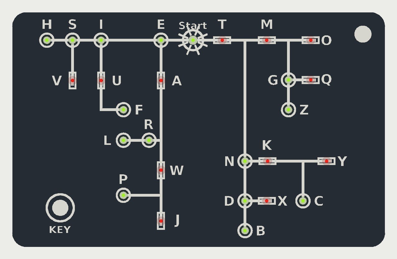
The pocket Morse decoder with no circuit board to order. A 3D-printed card the size of a bank card carries Dave Nathanson's decoding chart engraved in its face, with an SMD LED behind a window at every letter. Press the key short for a dot and long for a dash, and the letter you have reached lights.
Everything inside is hand-wired with enamelled copper wire to an Arduino Pro Mini, running on one CR2032 coin cell. The design has not been built yet.
고급
About 1 day, plus printing
안내
1
1
LED current and keying speed
LED current and keying speed
Jupyter 노트북 불러오는 중…
2
2
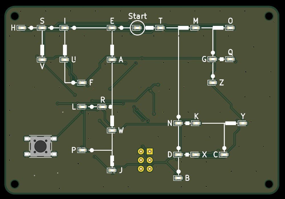
The same decoder on a circuit board
The same decoder on a circuit board
That version needs a board made to order. This one is printed and wired by hand.
3
3
Read the chart
Read the chart
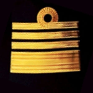
Dave Nathanson (KG6ZJO) drew his decoding chart in 2010: "Start with your finger at "Start Here". Then move your finger to track the Morse dots & dashes. You will arrive at the correct letter!" On this card the LEDs do the tracking: yellow-green at the dots, red at the dashes.
4
4
Print the card body
Print the card body
The card, 85.6 x 54 x 7.5 mm, with the chart engraved 0.5 mm deep, a window and LED pocket at each letter, the key hole, four screw bosses and the key-ring hole. Print it face down on a smooth bed: PLA, 0.12 mm layers, no supports.
5
5
Print the lid
Print the lid
The 1.2 mm back lid with four countersunk screw holes and the credit and instructions engraved. PLA, 0.12 mm layers, engraved side down.
6
6
Fit the LEDs
Fit the LEDs
Press a 1206 LED into each pocket from the back, lens towards the window: yellow-green at the 14 dot rings and at Start, red at the 12 dash marks. Note each LED's cathode mark, then fix it with a tiny drop of glue at its edge, keeping the pads clean.
이 단계의 재료:
 칩 LED27 개
 순간접착제(시아노아크릴레이트)1 개
필요한 도구:
 끝이 뾰족한 핀셋
 돋보기
 멀티미터
7
7
Wiring table
Wiring table
The 27 LEDs share six lines, D3 to D8, each LED between two of them. Wire each LED's + (anode) and - (cathode) pad to the lines below; the firmware expects exactly this.
| LED | Code | Colour | + (anode) to | - (cathode) to |
|---|---|---|---|---|
| Start | (none) | yellow-green | D3 | D4 |
| T | - | red | D4 | D3 |
| E | . | yellow-green | D4 | D5 |
| M | -- | red | D5 | D4 |
| N | -. | yellow-green | D5 | D6 |
| A | .- | red | D6 | D5 |
| I | .. | yellow-green | D6 | D7 |
| O | --- | red | D7 | D6 |
| G | --. | yellow-green | D7 | D8 |
| K | -.- | red | D8 | D7 |
| D | -.. | yellow-green | D3 | D5 |
| W | .-- | red | D4 | D6 |
| R | .-. | yellow-green | D5 | D3 |
| U | ..- | red | D5 | D7 |
| S | ... | yellow-green | D6 | D4 |
| Q | --.- | red | D6 | D8 |
| Z | --.. | yellow-green | D7 | D5 |
| Y | -.-- | red | D8 | D6 |
| C | -.-. | yellow-green | D3 | D6 |
| X | -..- | red | D4 | D7 |
| B | -... | yellow-green | D5 | D8 |
| J | .--- | red | D6 | D3 |
| P | .--. | yellow-green | D7 | D4 |
| L | .-.. | yellow-green | D8 | D5 |
| F | ..-. | yellow-green | D3 | D7 |
| V | ...- | red | D4 | D8 |
| H | .... | yellow-green | D7 | D3 |
8
8
Wire the card
Wire the card
Remove the Pro Mini's power LED. Solder a 150 Ω resistor to each of D3-D8 and run a 0.2 mm solderable enamelled wire from each resistor round the cavity as that line's bus. Solder short wires from every LED pad to its bus, as the wiring table says; the iron strips the enamel. Wire the key between D2 and GND, and the cell holder's + to VCC and - to GND. Check every LED with the meter's diode test.
이 단계의 재료:
 마이크로컨트롤러 보드1 개
 전기 저항6 개
 푸시 버튼1 개
 건전지 홀더1 개
 에나멜 피복 구리선1 개
 땜납 선1 개
필요한 도구:
 인두끝이 뾰족한 핀셋
 플럭스돋보기멀티미터
9
9
The firmware
The firmware
morse_card.ino: every timing is a named constant at the top. Board in the Arduino IDE: Arduino Pro or Pro Mini, ATmega328P (3.3V, 8 MHz).
morse_card.inoarduino
10
10
Upload
Upload
Take the cell out. Connect a 3.3 V USB-to-serial adapter to the Pro Mini's programming pins, choose Arduino Pro or Pro Mini, ATmega328P (3.3V, 8 MHz), and upload. Start lights; key E (one short press) and E lights.
필요한 도구:
 USB 시리얼 어댑터
 Arduino IDE가 설치된 컴퓨터
11
11
Close the card
Close the card
Glue the key into its hole, plunger through the face. Stick the Pro Mini and the cell holder to the lid's inside with double-sided tape, leaving the wires some slack, put a CR2032 in, and screw the lid on with four M2 x 6 self-tapping screws.
이 단계의 재료:
순간접착제(시아노아크릴레이트)1 개 양면 테이프1 개
 태핑 나사4 개
 CR2032 코인 전지1 개
 PLA 필라멘트1 개
필요한 도구:
 FDM 3D 프린터
 정밀 드라이버 세트
12
12
The build in 3D
The build in 3D
FreeCAD model of the card: the body with its engraved chart and LED windows, the lid, and the space taken by the Pro Mini, cell holder, key and screws, checked for clashes.
13
13
Troubleshooting
Troubleshooting
Printed Morse card troubleshooting.
Flow
Loading...
14
14
History and honest limits
History and honest limits
The chart is **Dave Nathanson**'s (KG6ZJO), drawn in 2010 and shared as copyleft. The letter codes are ITU-R M.1677-1's. The card, its sizes, parts, wiring and timings are ours. The model was checked for clashes and the firmware compiles with all 26 codes checked against ITU, but the card has not been printed, wired or tested.
재료
12- 27 개플레이스홀더
- 플레이스홀더
- 1 개플레이스홀더
- 6 개플레이스홀더
- 플레이스홀더
- 플레이스홀더
- 1 개플레이스홀더
- 1 개플레이스홀더
- 1 개플레이스홀더
- 4 개플레이스홀더
- 1 개플레이스홀더
- 1 개플레이스홀더
필요 도구
9- 플레이스홀더
- 플레이스홀더
- 플레이스홀더
- 2 vendors sell this, none ship to you yet플레이스홀더
- 플레이스홀더
- 3 vendors sell this, none ship to you yet플레이스홀더
- 플레이스홀더
- 플레이스홀더
- 플레이스홀더
이 블루프린트로 만드는 것
관련 블루프린트
이 블루프린트들은 지식을 공유합니다 — 기술, 재료 또는 원리

CC0 퍼블릭 도메인
이 블루프린트는 CC0로 공개되었습니다. 어떤 목적으로든 자유롭게 복사, 수정, 배포 및 사용할 수 있습니다.
제품 구매를 통해 메이커를 지원하세요. 판매자가 설정한 메이커 커미션 을 받거나, 이 블루프린트의 새로운 반복을 만들어 연결로 포함시킬 수 있습니다.