협업
예술
뷰티 및 웰니스
공예
문화 및 역사
엔터테인먼트
환경
음식 및 음료
역공학
과학
스포츠
기술
웨어러블
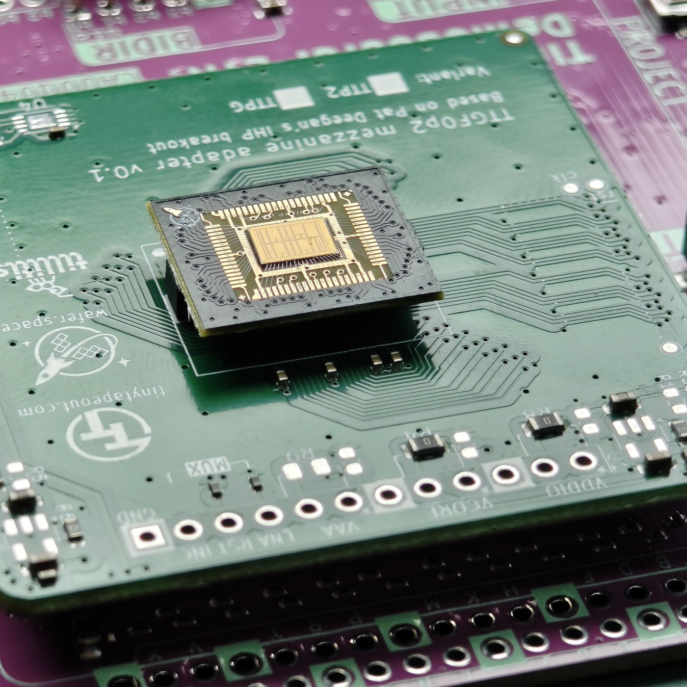


The Chip-on-Board Breakout: From a 0.4 mm Mezzanine to Pins You Can Reach
A chip from a shared wafer comes back tiny. On wafer.space's Run 1 it arrived as a chip-on-board part 14 × 16 mm, with the die wire-bonded under epoxy and a 70-pin mezzanine connector underneath at 0.4 mm pitch. Nothing on a bench can touch pins that small, so the first thing to build is a board that carries them back out.
wafer.space publishes example breakout motherboards in KiCad under Apache-2.0: one sheet, two boards. Each has the mating 70-pin mezzanine socket; one breaks the pins out to two 1 × 35 rows of 0.1-inch pin headers, the other to two rows of 35 castellated edge pads at 1 mm.
This rung works out why the fine pitch is needed and what spreading it out costs in board length, shows the published schematic, and builds the header version.
고급
About a day of soldering, plus board fabrication
안내
1
1
Pitch against board edge
Pitch against board edge
Jupyter 노트북 불러오는 중…
2
2
Where the chip comes from
Where the chip comes from
The embedded blueprint designs the chip and orders it. This rung builds the board it plugs into.
3
3
What the chip-on-board plugs into
What the chip-on-board plugs into
From wafer.space's Run 1 documentation: the full-slot chip-on-board is 14 × 16 mm; the die's 74 bond pads follow the Tiny Tapeout convention, and all grounds are tied together on the default breakout. It carries a 70-pin, 0.4 mm pitch mezzanine connector (LCSC C19089236; the mating part is LCSC C19089262).
So that every project fits the same boards, the default breakouts share the same wire-bonding layout, the same 14 × 16 mm footprint and the same connector position; traces, signal types and net assignments are left to the designer. wafer.space notes that pinouts, connectors and footprints are specific to each run.
4
4
The published breakout schematic
The published breakout schematic
wafer.space's example motherboards, from the chip-on-board-wire-bonded-pcbs repository (run-1/motherboards, Apache-2.0), shown as published. On the left, the ".1\" Header" board: the mezzanine socket J102 (HCTL HC-PBB40C-70DP-0.4V-02, 70 pins at 0.4 mm) broken out to the 1 × 35 pin headers J101 and J103 at 2.54 mm. On the right, the "Castellated" board: the same socket J105 broken out to the 1 × 35 castellated edges J104 and J106 at 1 mm, so the whole breakout can itself be soldered onto a larger board.
KiCanvas 뷰어 로딩 중...
전문 PCB 디자인 뷰어
5
5
Build the header board
Build the header board
Download the run-1/motherboards project from the repository and open it in KiCad. The files are saved by KiCad 10, so an older KiCad will not open them. Plot the Gerber and drill files and order the board from a PCB fabricator, with a solder-paste stencil for the mezzanine footprint.
Hold the stencil over the mezzanine pads and spread lead-free solder paste across it in one stroke. Place the socket with fine tweezers, square to its pads, and reflow it with the hot-air station until the paste flows and settles. Inspect every one of the 70 joints with the loupe; clear any bridge between neighbouring pins with flux and the iron or hot air.
Solder the two 1 × 35 pin headers with the iron. Before you plug in a chip, check with the multimeter that no two neighbouring header pins are shorted, and that each header pin reaches the socket pin the schematic connects it to.
이 단계의 재료:
 인쇄 회로 기판1 개
 보드 대 보드 커넥터1 개
 핀 헤더2 개
 솔더 페이스트 (무연)1 개
 주석-납 땜납1 개
 플럭스1 개
필요한 도구:
 열풍 리워크 스테이션
 인두
 끝이 뾰족한 핀셋
 확대 루페
 멀티미터
 데스크톱 컴퓨터
6
6
A breakout that shorts or does not connect
A breakout that shorts or does not connect
Breakout board troubleshooting.
Flow
Loading...
7
7
Sources and honest limits
Sources and honest limits
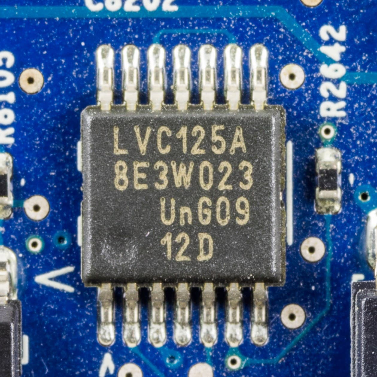
**Sources**, read 29 September 2026: wafer.space's chip-on-board-wire-bonded-pcbs repository (README, run-1/README and run-1/motherboards, Apache-2.0). The schematic in step 4 is theirs, unchanged. The photograph is theirs too, from the same repository: a Run 1 chip-on-board seated on a Tiny Tapeout mezzanine adapter board (TTGF02, v0.1), not the header board built in step 5.
**Honest limits.** This rung has not been built for this blueprint; the soldering steps are standard practice for a 0.4 mm surface-mount connector, not wafer.space instructions. The pinout and footprint are Run 1's, and wafer.space says they are expected to change in later runs, so check the current run's documentation before ordering boards.
재료
6- 1 개플레이스홀더
- 1 개플레이스홀더
- 플레이스홀더
- 1 개플레이스홀더
- 1 개플레이스홀더
- 1 개플레이스홀더
관련 블루프린트
이 블루프린트들은 지식을 공유합니다 — 기술, 재료 또는 원리


CC0 퍼블릭 도메인
이 블루프린트는 CC0로 공개되었습니다. 어떤 목적으로든 자유롭게 복사, 수정, 배포 및 사용할 수 있습니다.
제품 구매를 통해 메이커를 지원하세요. 판매자가 설정한 메이커 커미션 을 받거나, 이 블루프린트의 새로운 반복을 만들어 연결로 포함시킬 수 있습니다.