

Centrifugal Governor
An engine with no governor speeds up when the load comes off and slows when it goes on. A mill driven by one produces uneven cloth; a lathe cuts unevenly; a threshing machine jams. Somebody has to stand at the throttle all day.
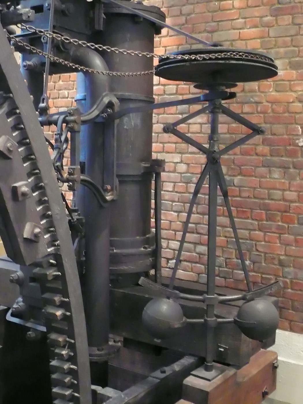
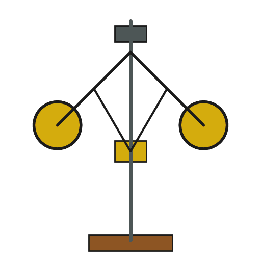
The governor removes that person. Two weighted balls hang from a spindle driven by the engine. Spin faster and they swing outward; the linkage they carry pulls the throttle closed. Slow down and they drop, and the throttle opens again. The machine measures its own speed and corrects it, with no measurement, no decision and no operator anywhere in the loop.
Build it as a hand-cranked model and you can see the whole idea in thirty seconds: the disturbance itself supplies the correction. That is feedback control, and this is the object that put it into industry.
คำแนะนำ
Mount a vertical spindle in two bearings
Mount a vertical spindle in two bearings
Fit a 6 mm steel rod vertically in two bearings on a baseboard so it turns freely and cannot wobble. Everything hangs off this spindle, so slop here shows up as vibration everywhere.
วัสดุสำหรับขั้นตอนนี้:
 แท่งเหล็กกลมคาร์บอนต่ำ1 ชิ้น
Fix a collar near the top
Fix a collar near the top
Clamp a fixed collar to the spindle 40 mm below the top. The upper arms pivot from this collar and it never moves.
Fit a sliding sleeve below it
Fit a sliding sleeve below it
Fit a second collar that slides freely up and down the spindle while turning with it. This sleeve is the output of the whole machine — its height is the measurement of speed.
Make two arms with weights
Make two arms with weights
Cut two arms 120 mm long and fix an equal mass to the end of each — steel balls or nuts of 60-100 g. The two must match in mass and length or the assembly runs out of balance.
วัสดุสำหรับขั้นตอนนี้:
 ตลับลูกปืนเหล็ก2 ชิ้น
เครื่องมือที่ต้องใช้:
 เครื่องชั่งดิจิทัล
Hinge the arms to the fixed collar
Hinge the arms to the fixed collar
Pin each arm to the fixed collar so it swings only outward and inward in a vertical plane, freely, with no stiffness in the joint.
Link the arms to the sliding sleeve
Link the arms to the sliding sleeve
Connect each arm to the sliding sleeve with a short link pinned at both ends. Now when the arms rise, the sleeve is pulled up; when they fall, it drops.
Check the geometry through its full travel
Check the geometry through its full travel
Lift the arms by hand from hanging to nearly horizontal and confirm nothing binds or goes over centre. A governor that jams at one end of its travel is worse than none at all.
Drive the spindle
Drive the spindle
Drive the spindle from a hand crank through a belt or a pair of gears. A crank is enough to demonstrate everything; a small motor with a speed control is better for measurement.
Find the speed at which the arms lift
Find the speed at which the arms lift
Turn slowly and increase speed until the arms just begin to rise. Count turns against a stopwatch and write the figure down. Below this speed the weights simply hang.
เครื่องมือที่ต้องใช้:
 นาฬิกาจับเวลา
Plot sleeve height against speed
Plot sleeve height against speed
Measure the sleeve height at five different speeds and plot the two against each other. The curve is the governor's characteristic — every mechanism that follows depends on this one relationship.
เครื่องมือที่ต้องใช้:
 ไม้บรรทัด
Change the ball mass and re-measure
Change the ball mass and re-measure
Swap in heavier balls and repeat. Heavier weights do not simply lower the lift-off speed the way most people predict — take the measurements rather than guessing, and compare against your first curve.
Change the arm length and re-measure
Change the arm length and re-measure
Now change the arm length instead, keeping the same balls. Arm length shifts the whole curve — this is the adjustment an engineer actually used to set an engine's working speed.
Connect the sleeve to a throttle plate
Connect the sleeve to a throttle plate
Link the sliding sleeve through a bell crank to a pivoting flap standing in for the steam valve, arranged so rising sleeve closes the flap. Get that sense the wrong way round and the mechanism drives the engine to destruction instead of steadying it.
Demonstrate the correction
Demonstrate the correction
Crank faster and watch the flap close; slow down and watch it open. Nothing is being measured or decided — the same rotation that is the problem is also the sensor.
Make it hunt
Make it hunt
Lengthen the linkage or add mass to the sleeve, and the governor starts to overshoot and oscillate around its speed instead of settling. That instability is called hunting, and provoking it deliberately is the most useful thing this model does.
Damp the hunting
Damp the hunting
Add friction at the sleeve or a light spring against its travel, and the oscillation dies away. You have just built, by hand, the fix that nineteenth-century engineers spent decades formalising.
History & Context
History & Context
Not Watt's invention. Christiaan Huygens described a centrifugal governor in the seventeenth century, and the device was already in use on windmills and water wheels, where it regulated the gap and pressure between millstones as the sails turned faster or slower. James Watt designed his first governor in 1788, at the suggestion of his partner Matthew Boulton, adapting the mill mechanism to the steam engine. He is often called its inventor; he was its most consequential adopter.
Why the steam engine needed it more than the mill did. A windmill's speed is set by weather. A steam engine's speed is set by its load, which in a factory changes every time a machine is engaged or disengaged. Constant speed under changing load is what makes a single engine able to drive a whole mill through line shafting — and the governor is what delivers it.
The limit built into the mechanism. A simple governor cannot hold exactly one speed. To open the throttle further it must let the balls sit lower, and the balls only sit lower if the engine is running slower. So a heavier load settles at a slightly lower speed than a light one. The governor shrinks the variation rather than abolishing it — a property later called droop, and the reason proportional control alone is never quite enough.
Then it became mathematics. As engines ran faster, governors began to hunt, and nobody could say in advance which designs would be stable. James Clerk Maxwell answered that in 1868 with a paper called On Governors, analysing the motion as a differential equation and deriving conditions for stability. It is a founding document of control theory. The line from a pair of spinning brass balls to modern feedback control runs straight through that paper.
วัสดุ
2- 1 ชิ้นตัวยึดตำแหน่ง
- 2 ชิ้นตัวยึดตำแหน่ง
เครื่องมือที่จำเป็น
3- ตัวยึดตำแหน่ง
- ตัวยึดตำแหน่ง
- ตัวยึดตำแหน่ง
วัสดุจากพิมพ์เขียวที่เชื่อมต่อ
พิมพ์เขียวนี้สร้าง
CC0 สาธารณสมบัติ
พิมพ์เขียวนี้เผยแพร่ภายใต้ CC0 คุณสามารถคัดลอก แก้ไข แจกจ่าย และใช้งานผลงานนี้เพื่อวัตถุประสงค์ใดก็ได้ โดยไม่ต้องขออนุญาต
สนับสนุนเมกเกอร์โดยซื้อสินค้าผ่านพิมพ์เขียวของพวกเขา ซึ่งพวกเขาจะได้รับ ค่าคอมมิชชันเมกเกอร์ ที่ผู้ขายกำหนด หรือสร้างเวอร์ชันใหม่ของพิมพ์เขียวนี้และรวมเป็นการเชื่อมต่อในพิมพ์เขียวของคุณเพื่อแบ่งรายได้