ARTE
BELLEZA Y BIENESTAR
ARTESANÍA
CULTURA E HISTORIA
ENTRETENIMIENTO
MEDIO AMBIENTE
COMIDA Y BEBIDAS
INGENIERÍA INVERSA
CIENCIAS
DEPORTES
TECNOLOGÍA
TECNOLOGÍA VESTIBLE
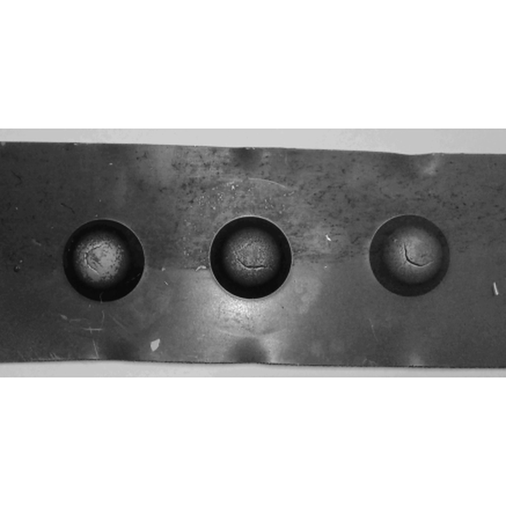


How Far a Sheet Will Stretch: The Cupping Test and the Circle Grid
You can buy two sheets of 1 mm aluminium with the same thickness, the same alloy number and the same certificate, and one of them will make your part while the other splits.
The difference is **formability**, and no ordinary specification captures it. Tensile strength does not; hardness does not. What a press asks is a different question: how far can this metal stretch over a punch before it necks, and will it pull metal in from the flange rather than thinning the wall?
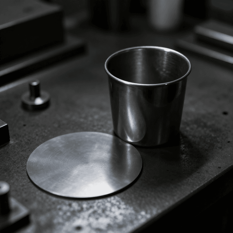
A. M. Erichsen answered it in 1912 with a test so simple it is still an ISO standard: press a 20 mm ball into a clamped disc and write down how deep it goes before it cracks. The photograph on this page is a strip that has been through it — two good cups and one that split. This rung runs that test, then learns the technique that reads strain off a real part.
Intermedio
About 3 hours
Instrucciones
1
1
Build a cupping rig you can actually clamp
Build a cupping rig you can actually clamp
The standard calls for a 20 mm hemispherical punch, a 27 mm die opening and a blank holder gripping a 90 mm disc at a set force. You will not reproduce that exactly, and it does not matter provided you keep **your own** rig identical between samples — this is a comparative test, not an absolute one.
What you need:
- **A punch.** A 20 mm ball bearing, or a bolt head turned to a dome. The nose must be smooth; any scratch prints itself into the metal and starts the crack there.
- **A die.** A plate with a 27 mm hole, its edge radiused — about 2 mm — not sharp. A sharp die edge cuts the blank instead of letting it draw, and you will measure the wrong thing.
- **A blank holder.** A second plate with the same hole, bolted down onto the first with the blank between them. Four bolts, tightened evenly with the torque wrench to the same figure every time. This is the part that decides whether your results are comparable.
Cut discs of each material you want to test, all the same diameter, all deburred, all measured with the micrometer and the actual thickness written on each one in marker.
Lubricate the punch with the same amount of the same grease every time — lanolin or beeswax is traditional and works. Lubrication changes the answer substantially, so it becomes part of the procedure rather than a detail.
Materiales para este paso:
 Placa de acero dulce1 pieza
 Lámina de acero galvanizado de 0,9 mm1 pieza
 Chapa de aluminio1 pieza
 Lámina de latón1 pieza
Herramientas necesarias:
 Taladro de columna
 Prensa hidráulica
 Prensa de husillo
 Tornillo de banco
 Limas (lima de mano)
 Micrómetro
 Calibre digital de 6 pulgadas
 Desbarbador
 Rotulador permanente
 Gafas de seguridad transparentes
 Guantes de trabajo de cuero
 Cuaderno de laboratorio (con copia)
 Lanolina
2
2
Press the ball in until it splits
Press the ball in until it splits
Clamp a disc in the rig, set it under the press with the punch centred, and press **slowly**. Watch the top surface of the growing dome.
What you will see, in order:
1. The dome rises smoothly and the surface stays bright.
2. At some depth the surface goes **matt and slightly orange-peel** near the crown. That is the grains deforming individually, and it means the metal there is well into plastic strain.
3. A faint **neck** appears — a local line where the metal is thinning faster than its surroundings. On a good specimen this is visible a moment before failure.
4. A through-crack, usually a short arc, usually around the crown rather than at it.
Stop at the first through-crack and measure the depth: the distance the punch travelled from first contact. A depth gauge on the press ram, or the calipers on the formed cup, both work provided you do it the same way each time.
Run at least three discs of each material and take the mean. Then compare: the softest material will go deepest, and the hardest will crack early and suddenly — a 6061-T6 coupon may split with almost no warning where an annealed brass one necks visibly first.
Anneal a coupon of brass or copper and test it against an un-annealed one from the same sheet. The difference is the single most convincing demonstration in this rung, and it explains why almost every deep-drawn part in history was made from annealed stock.
Stand to the side of the press. A specimen cracks suddenly and the punch drops; keep hands out from under and wear a face shield as well as glasses.
Materiales para este paso:
Chapa de aluminio2 piezasLámina de latón2 piezas Lámina de cobre2 piezasLámina de acero galvanizado de 0,9 mm2 piezas
Herramientas necesarias:
Prensa hidráulicaPrensa de husilloCalibre digital de 6 pulgadasMicrómetro Microscopio digitalRotulador permanente
 Pantalla facialGafas de seguridad transparentesGuantes de trabajo de cueroCuaderno de laboratorio (con copia)Lanolina
3
3
Print a circle grid and read the strain off a formed part
Print a circle grid and read the strain off a formed part
The cupping test compares materials. Circle grid analysis tells you about **a part**, and it is the technique that turns a split panel into a diagnosis.
Mark a grid of small circles on a fresh blank — 2.5 mm diameter is a good size. Options, cheapest first: a template and a fine permanent marker; a stencil and layout fluid scratched through with a scriber; or a rubber stamp cut from an eraser. Industry electro-etches them; you do not need to.
Form the blank — in your cupping rig, or over one of the form blocks from rung 7 — and then measure what the circles became. Each one is now an ellipse. With the calipers or under the microscope, record the **major** and **minor** axes of circles at four places: on the flat flange, on the crown over the punch, on the side wall, and at any tight corner.
Step 5 turns those pairs into major strain, minor strain and — the interesting one — **thinning**, which you never measured. The metal's volume did not change, so the thickness strain is whatever the other two leave over.
The pattern you are looking for is this. A circle that grew in **both** directions was stretched, and it thinned badly. A circle that grew in one direction and **shrank** in the other was drawn, and it hardly thinned at all, because the metal it needed came from its own width rather than from its thickness.
That distinction — stretching against drawing — is the thing every rung in this batch has been circling, and here it is measurable with a marker pen and a magnifier.
Materiales para este paso:
Chapa de aluminio1 piezaHerramientas necesarias:
 Punta de trazar de diamanteRotulador permanenteMicroscopio digitalCalibre digital de 6 pulgadas
 ReglaPrensa hidráulicaGafas de seguridad transparentesCuaderno de laboratorio (con copia)
 Solución de pavonado de metal
4
4
Find the grain direction's fingerprint: earing
Find the grain direction's fingerprint: earing
Draw a cup — in the cupping rig, pressed right through rather than stopped at a crack, or using the deep-drawing rung's tooling if you have it — and look at the rim.
It is not level. There are usually four raised **ears**, and they sit at a repeatable angle to the rolling direction. That is *planar anisotropy*: the sheet's r-value is different at 0°, 45° and 90° to the grain, so the metal draws in more easily in some directions than others and the rim ends up scalloped.
Measure it. Mark the rolling direction on the blank before you draw it. Then measure the cup height at 0°, 45°, 90° and 135°, and compute the earing as (max − min) / mean. A few per cent is normal; ten per cent means a lot of metal is going to be trimmed off and thrown away.
Two practical consequences:
1. **A drawn part needs a trim allowance**, and the allowance is set by the earing, not by the drawing tolerance.
2. **Anneal between draws.** Every draw work-hardens the metal; a second draw on unannealed metal splits at a depth the first one managed easily. This is why the deep-drawing rung's cartridge cases go through a sequence of draws with a furnace between each one.
Note also which way the ears point relative to your marked rolling direction, and write it down with the material. It is a property of that sheet and it will be the same on the next part you make from it.
Materiales para este paso:
Chapa de aluminio1 piezaLámina de latón1 piezaHerramientas necesarias:
Prensa hidráulicaCalibre digital de 6 pulgadasRegla Escuadra combinadaRotulador permanenteMicroscopio digitalGafas de seguridad transparentesCuaderno de laboratorio (con copia)
5
5
n, r, cupping depth and the circle grid
n, r, cupping depth and the circle grid
Cargando el cuaderno de Jupyter…
Herramientas necesarias:
 Papel milimetrado
6
6
History and context
History and context
**Attribution, stated honestly.** The cupping test is **A. M. Erichsen's**, applied for in **December 1912** and granted in 1913 as a British patent. **No number is asserted here**: the sources reachable from this bench give the number inconsistently, and an unverified number in a blueprint is worse than none at all. The test itself is not in doubt — it is **ISO 20482** today, and the company Erichsen founded still makes the machines.
**Why a crude test won.** By 1912 the tensile test was a century old and thoroughly understood, and it was useless for predicting whether a sheet would press. Erichsen's answer was not to model the problem but to **reproduce it in miniature**: clamp a disc, push a ball into it, measure the depth. It is comparative rather than absolute, it depends on lubricant and tooling, and none of that stopped it becoming the standard acceptance test for sheet for the next century — because it asks the same question the press asks.
That is a pattern worth naming. When a property is hard to predict from first principles, a **standardised imitation of the real operation** often beats a better theory of a different operation.
**What came after.** The forming limit diagram of the 1960s — Keeler and Goodwin's work — generalises this: instead of one depth number, a curve in major-strain / minor-strain space separating what survives from what splits. Circle grid analysis in step 3 is how a real part is placed on that curve, and it is still exactly how press shops diagnose a split panel.
**Honest limits.** The cupping number is not a design input. It depends on thickness, lubricant, punch finish and clamp force, so it compares batches of the same material on the same rig and nothing else. It is a **stretch** test, so it says little about a deep draw, where the r-value matters more. And the home-built rig in step 1 will not give numbers comparable with anybody else's — which is fine, because the comparison you need is between your own sheets.
Materiales
5- 1 piezaMarcador de posición
- Marcador de posición
- 2 piezasMarcador de posición
- 2 piezasMarcador de posición
- 2 piezasMarcador de posición
Herramientas requeridas
20- Marcador de posición
- Marcador de posición
- Marcador de posición
- Marcador de posición
- Marcador de posición
- Marcador de posición
- Marcador de posición
- Marcador de posición
- Marcador de posición
- Marcador de posición
- Marcador de posición
- Cuaderno de laboratorio (con copia)10% de comisiónMarcador de posición
- Marcador de posición
- Marcador de posición
- Marcador de posición
- Marcador de posición
- Marcador de posición
- Solución de pavonado de metal10% de comisiónMarcador de posición
- Marcador de posición
- Marcador de posición
Blueprints relacionados
Estos blueprints comparten conocimiento — técnicas, materiales o principios



CC0 Dominio público
Este Blueprint se publica bajo CC0. Eres libre de copiar, modificar, distribuir y usar este trabajo para cualquier propósito, sin pedir permiso.
Apoya al Maker comprando productos a través de su Blueprint, donde gana una Comisión del Maker establecida por los vendedores, o crea una nueva iteración de este Blueprint e inclúyela como conexión en tu propio Blueprint para compartir ingresos.