Kerjasama
SENI
KECANTIKAN & KESEJAHTERAAN
KRAFTANGAN
BUDAYA & SEJARAH
HIBURAN
ALAM SEKITAR
MAKANAN & MINUMAN
KEJURUTERAAN TERBALIK
SAINS
SUKAN
TEKNOLOGI
BOLEH PAKAI
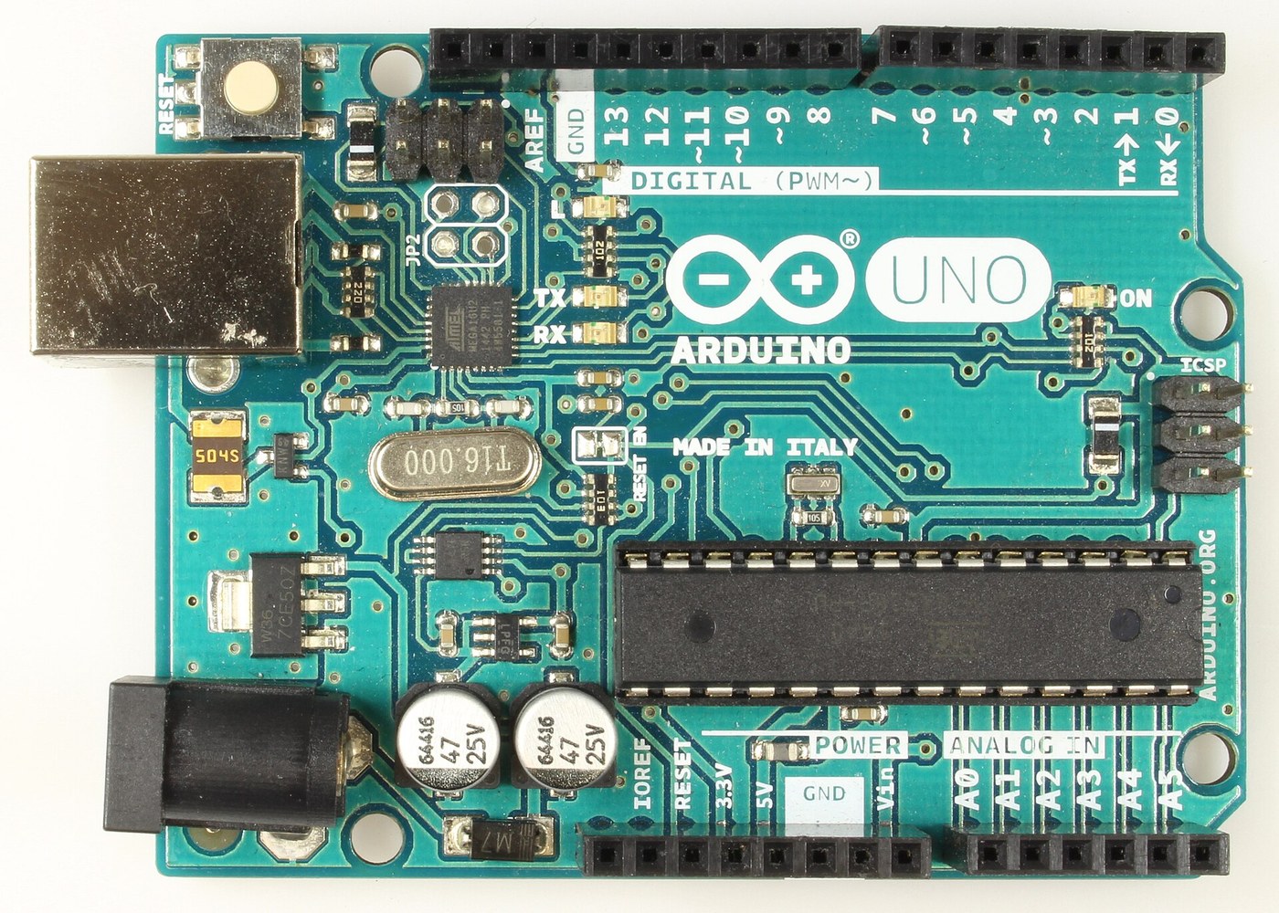


Arduino Uno R3: Assembled from Arduino's Open UNO-TH Rev3e Design Files and Flashed over ICSP
The Arduino Uno R3 is open hardware: Arduino publishes its schematic and board layout. This blueprint builds one from those files, part by part, then loads the firmware into its two processors.
Result: an Arduino Uno R3. An ATmega328P (16 MHz, 32 kB flash, 2 kB SRAM, 1 kB EEPROM) runs your programs; an ATmega16U2 turns USB into its serial link. It runs from USB (5.5 V at most) or 6-20 V at the DC jack.
Source: Arduino UNO-TH_Rev3e design files and the A000066 schematic and datasheet (Arduino, CC BY-SA). Unknown: how every bought part is made; no public source in hand says. The soldering method is ours. Picture: Wikimedia Commons.
Lanjutan
1 day
Arahan
1
1
Get the bare board
Get the bare board
Have the two-layer board made to Arduino's UNO-TH_Rev3e board layout (the .brd file of the design files). Check it against the schematic before fitting anything.
Bahan untuk langkah ini:
 Papan litar bercetak1 UNO-TH Rev3e layout
Alatan diperlukan:
 Kanta Pembesar Tukang Emas
2
2
Fit the small surface-mount parts
Fit the small surface-mount parts
Solder the chip parts to their marked places: resistor arrays RN1 (10K), RN2 and RN4 (1K), RN3 (22R); R1, R2 (1M); capacitors C1, C2, C4-C7, C10 (100n), C3, C8 (1u), C9, C11 (22p); varistors Z1, Z2; ferrite bead L1; inductor L2 (10 uH); diodes D2, D3; LEDs ON (green), L, RX, TX (yellow). Ours: flux, tweezers and hot air or a fine iron, checked under a loupe.
Bahan untuk langkah ini:
 Tatasusunan perintang cip4 RN1-RN4
 Perintang cip2 1M
 Kapasitor seramik cip11 7x100n, 2x1u, 2x22p
 Varistor cip2 Z1, Z2
 Manik ferit1 L1
 Induktor lekap permukaan1 L2
 Diod lekap permukaan2 D2, D3
 LED cip4 1 green, 3 yellow
 Dawai Pateri1 a little
Alatan diperlukan:
 Fluks
 Penyepit berhujung tirus
 Stesen kerja semula udara panas
 Alat pematerianKanta Pembesar Tukang Emas
3
3
Fit the power and chip parts
Fit the power and chip parts
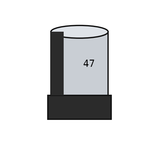
Solder the ATmega16U2 (U3), the 16 MHz resonator Y2 and crystal Y1, the 5 V regulator NCP1117 (U1) and 3.3 V regulator LP2985 (U2), the LMV358 op-amp (U5), the FDN340P transistor (T1), the M7 diode (D1), the 500 mA resettable fuse (F1) and the 47 uF capacitors PC1, PC2 with their polarity as marked.
Bahan untuk langkah ini:
 Pengawal mikro ATmega16U21 U3
 Resonator seramik piezoelektrik1 Y2
 Kristal kuarza1 Y1
 Pengatur voltan linear2 U1 5 V, U2 3.3 V
 IC penguat kendalian1 U5 LMV358
 MOSFET saluran-P1 T1Diod lekap permukaan1 D1 M7
 Fius boleh set semula1 F1
 Kapasitor cip berkutub2 PC1, PC2Dawai Pateri1 a little
Alatan diperlukan:
FluksPenyepit berhujung tirusStesen kerja semula udara panasAlat pematerianKanta Pembesar Tukang Emas4
4
Fit the through-hole parts
Fit the through-hole parts
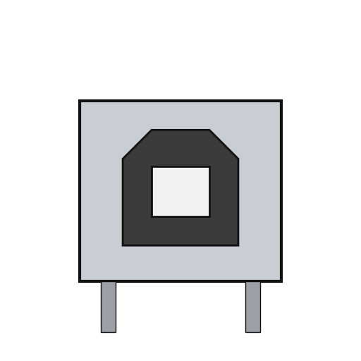
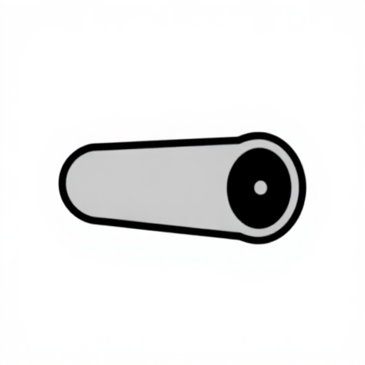
Solder the USB-B socket (X2), the DC jack (X1), the reset switch, the female headers (one 10-way, two 8-way, one 6-way) and the two 2x3 ICSP headers. Seat the ATmega328P in its place (ZU4).
Bahan untuk langkah ini:
 Soket USB-B1 X2
 Soket kuasa tong1 X1
 Butang tekan1 RESET
 Pin pengepala6 10x1, 2x 8x1, 6x1 female; 2x 3x2 ICSP
 Pengawal mikro ATmega328P1 ZU4Dawai Pateri1 as needed
Alatan diperlukan:
Alat pematerian5
5
Flash and check
Flash and check
Check with a meter that 5 V and GND are not shorted. Through the ICSP headers, load the USB-to-serial firmware into the ATmega16U2 and the bootloader into the ATmega328P. Plug in USB: the green ON LED lights, and the blink test in the next step flashes the L LED. Ours: an AVR ISP programmer and a multimeter.
Bahan untuk langkah ini:
 Perisian tegar Arduino Uno1 download
Alatan diperlukan:
 Multimeter
 Pengatur cara AVR ISP
 Kabel USB-B
6
6
The blink test
The blink test
blink_test.ino: the same check as Arduino's Blink example. Upload it over USB from the Arduino IDE with the board set to Arduino Uno; the L LED on pin 13 turns on for one second and off for one second, over and over. If it does, both processors, the USB link and the bootloader work.
blink_test.inocpp
Alatan diperlukan:
Kabel USB-BBahan
24- 1 UNO-TH Rev3e layoutPemegang Tempat
- 4 RN1-RN4Pemegang Tempat
- 2 1MPemegang Tempat
- 11 7x100n, 2x1u, 2x22pPemegang Tempat
- 2 Z1, Z2Pemegang Tempat
- 1 L1Pemegang Tempat
- Pemegang Tempat
- 1 D1 M7Pemegang Tempat
- 4 1 green, 3 yellowPemegang Tempat
- 1 as neededPemegang Tempat
- Pemegang Tempat
- Pemegang Tempat
- 1 Y1Pemegang Tempat
- 2 U1 5 V, U2 3.3 VPemegang Tempat
- 1 U5 LMV358Pemegang Tempat
- 1 T1Pemegang Tempat
- Pemegang Tempat
- 2 PC1, PC2Pemegang Tempat
- 1 X2Pemegang Tempat
- Pemegang Tempat
- Pemegang Tempat
- Pemegang Tempat
- Pemegang Tempat
- 1 downloadPemegang Tempat
Alatan Diperlukan
8- Pemegang Tempat
- Pemegang Tempat
- Pemegang Tempat
- Pemegang Tempat
- 2 vendors sell this, none ship to you yetPemegang Tempat
- Pemegang Tempat
- Pemegang Tempat
- 1 vendor sell this, none ship to you yetPemegang Tempat
Blueprint ini membuat
Blueprint berkaitan
Blueprint ini berkongsi pengetahuan — teknik, bahan atau prinsip
CC0 Domain Awam
Blueprint ini dikeluarkan di bawah CC0. Anda bebas menyalin, mengubah, mengedar, dan menggunakan karya ini untuk sebarang tujuan, tanpa meminta kebenaran.
Sokong Pembuat dengan membeli produk melalui Blueprint mereka di mana mereka memperoleh Komisen Pembuat ditetapkan oleh Penjual, atau cipta iterasi baru Blueprint ini dan sertakan ia sebagai sambungan dalam Blueprint anda sendiri untuk berkongsi hasil.