Kerjasama
SENI
KECANTIKAN & KESEJAHTERAAN
KRAFTANGAN
BUDAYA & SEJARAH
HIBURAN
ALAM SEKITAR
MAKANAN & MINUMAN
KEJURUTERAAN TERBALIK
SAINS
SUKAN
TEKNOLOGI
BOLEH PAKAI
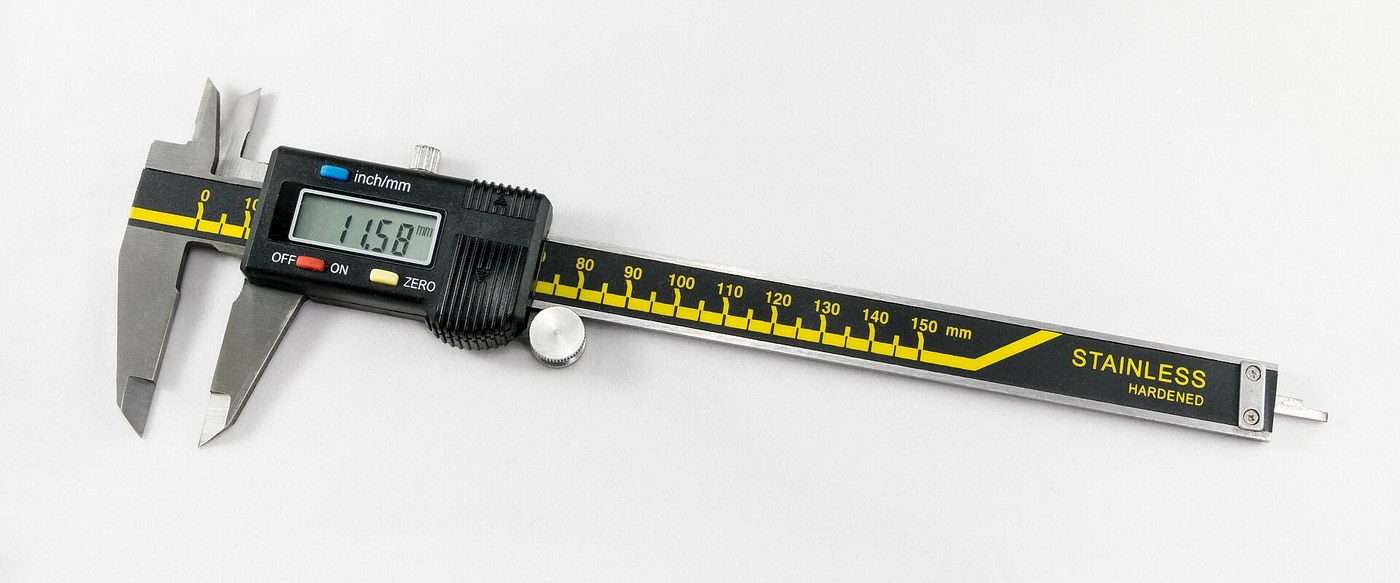


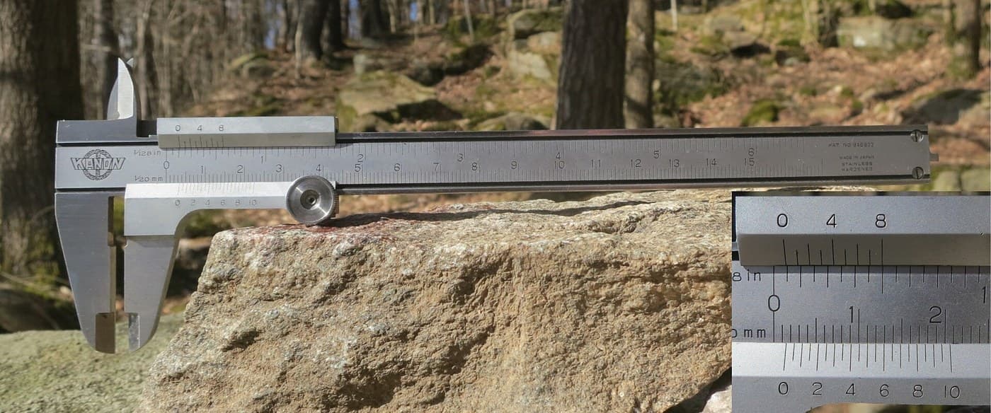
Digital Caliper: Capacitive Scale and Slider with Two-Chip Electronics (Baxter and Buehler, Starrett, 1986)
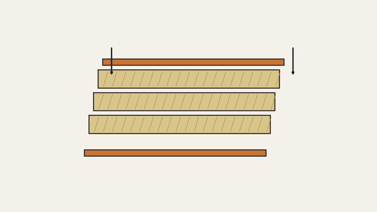
A six-inch caliper that reads out on a display. Under the slide, a strip of etched copper bars runs along the beam. Electrodes on the slider pass a signal through the bars by capacitance, and the slider's electronics count the bars crossed and work out the position in between.
Result: a digital caliper reading in inches or millimetres, repeatable to a ten-thousandth of an inch, with floating zero, peak hold and high/low limits. It runs on two 1.5 V cells at 10-50 microamps.
Source: L. K. Baxter and R. J. Buehler (L. S. Starrett Co.), US Patent 4,586,260 (1986). Unknown: the metal of the beam, slide and rod, their dimensions, the processor's program, and how the chips and display are made. Ours: the etchant, photoresist and glue. Picture: Wikimedia Commons.
Lanjutan
2 days
Arahan
1
1
Etch the scale
Etch the scale
Etch the scale pattern onto a strip of copper-clad epoxy fibreglass with photoresist and etchant. Each copper bar is 0.40 inch long, with a wider centre 0.12 inch long and two ends 0.14 inch long. Space the bars on 0.05 inch centres: the centres sit 0.004 inch apart, the ends 0.025 inch apart. Run the pattern the full length of the scale. Ours: dry film resist and ferric chloride.
Bahan untuk langkah ini:
 Papan PCB kosong (bersalut kuprum)1 strip, length of the beam
Alatan diperlukan:
 Fotorintang filem kering
 Larutan ferik klorida
 Sarung Tangan Kalis Kimia
2
2
Fix the scale into the beam
Fix the scale into the beam
The beam is a metal bar with the fixed outside and inside jaws at one end, a wide shallow channel in its face and a second channel along its back. Fix the scale permanently into the face channel, copper up. The patent allows etching before or after this step. Not given: the metal, the dimensions and how the scale is fixed. Ours: epoxy.
Bahan untuk langkah ini:
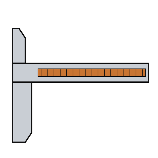 Batang angkup vernier1 with integral jaws
 Epoksi dua komponen1 a little
Alatan diperlukan:
 Dimensi tidak diketahui
3
3
Fit the parts to the circuit
Fit the parts to the circuit
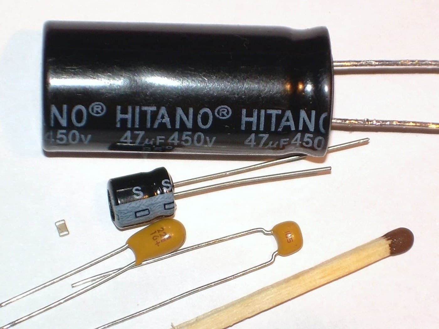
The circuit is one folded piece: a double-sided slider board joined by a flexible hinge to a circuit board. Its bottom face has two pickup electrodes, 0.750 x 0.110 inch and 0.0625 inch apart. On each side of them is an interdigitated transmitter array: fingers 0.115 inch long on 0.025 inch spacing, opening to 0.0375 inch at the centre. On the circuit board, solder or wire-bond the two chips: an NEC uPD7503 3 V processor (768 bits RAM, 2 kB ROM) and a CMOS gate array. Then fit the LCD, the 100 kHz crystal, the integrating capacitor and the MODE and SET buttons. Not given: the processor's program. Ours: a capacitor from a kit.
Bahan untuk langkah ini:
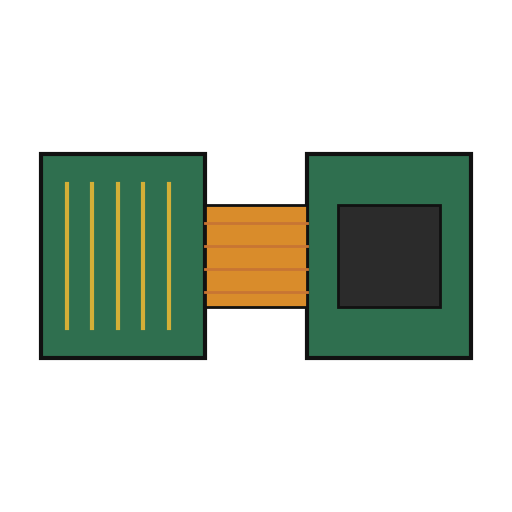 Papan litar tegar-fleksibel1 slider board + circuit board
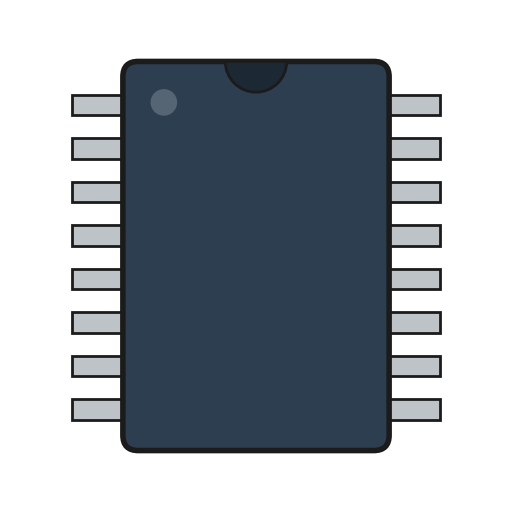 Litar bersepadu2 uPD7503 CPU, CMOS gate array
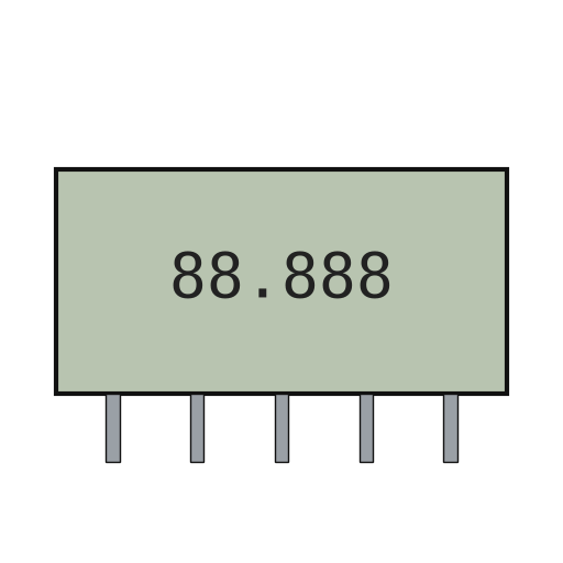 Panel LCD segmen1 5 digits
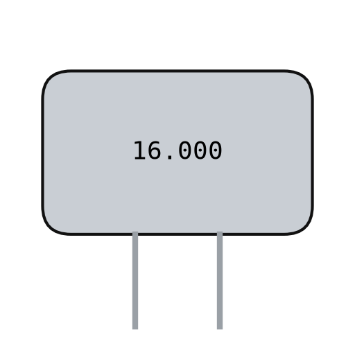 Kristal kuarza1 100 kHz
 Kit Kapasitor1 one integrating capacitor
 Butang tekan2 MODE, SET
 Dawai Pateri1 a little
Alatan diperlukan:
 Alat pematerian
4
4
Build the slide
Build the slide
The slide frame wraps the back and edges of the beam and carries the movable jaws. Fix it to the depth rod, which runs in the back channel of the beam; the rod's free end is the depth gauge. Put the moulded plastic housing between the frame ends. Fasten two metal wear strips under the slider board, one on each side of the scale. They ride on the beam and connect the board's copper to it. Not given: the metal and sizes.
Bahan untuk langkah ini:
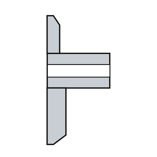 Rangka gelangsar1 with jaws
 Logam tidak diketahui1 depth rod and two wear strips
 Perumah gelangsar1 keping
Alatan diperlukan:
Dimensi tidak diketahui Set pemutar skru jitu
5
5
Assemble and check
Assemble and check
Fold the circuit into the housing recess, slider board facing the scale, and screw it to the frame. The electrodes must lie parallel to the scale bars at every point of travel. Put the two 1.5 V cells (the patent says 'zinc oxide') in the battery pockets of the circuit. The display shows five digits, a ten-thousandths bar graph, a minus sign and 'mm', plus PEAK, LOW, HIGH and LIMIT. Ours: check the reading against a vernier caliper.
Bahan untuk langkah ini:
 Skru mesin2 keping
 Bateri butang 1.5 V2 keping
Alatan diperlukan:
Set pemutar skru jitu Angkup Vernier
Bahan
15- 1 strip, length of the beamPemegang Tempat
- 1 with integral jawsPemegang Tempat
- 1 a littlePemegang Tempat
- 1 slider board + circuit boardPemegang Tempat
- 2 uPD7503 CPU, CMOS gate arrayPemegang Tempat
- 1 5 digitsPemegang Tempat
- 1 100 kHzPemegang Tempat
- 1 one integrating capacitorPemegang Tempat
- Pemegang Tempat
- 1 a littlePemegang Tempat
- 1 with jawsPemegang Tempat
- 1 depth rod and two wear stripsPemegang Tempat
- 1 kepingPemegang Tempat
- 2 kepingPemegang Tempat
- 2 kepingPemegang Tempat
Alatan Diperlukan
7- Pemegang Tempat
- Pemegang Tempat
- Pemegang Tempat
- Pemegang Tempat
- 2 vendors sell this, none ship to you yetPemegang Tempat
- Pemegang Tempat
- Pemegang Tempat
Bahan Blueprint Bersambung

Blueprint ini membuat

Blueprint berkaitan
Blueprint ini berkongsi pengetahuan — teknik, bahan atau prinsip
CC0 Domain Awam
Blueprint ini dikeluarkan di bawah CC0. Anda bebas menyalin, mengubah, mengedar, dan menggunakan karya ini untuk sebarang tujuan, tanpa meminta kebenaran.
Sokong Pembuat dengan membeli produk melalui Blueprint mereka di mana mereka memperoleh Komisen Pembuat ditetapkan oleh Penjual, atau cipta iterasi baru Blueprint ini dan sertakan ia sebagai sambungan dalam Blueprint anda sendiri untuk berkongsi hasil.