Kerjasama
SENI
KECANTIKAN & KESEJAHTERAAN
KRAFTANGAN
BUDAYA & SEJARAH
HIBURAN
ALAM SEKITAR
MAKANAN & MINUMAN
KEJURUTERAAN TERBALIK
SAINS
SUKAN
TEKNOLOGI
BOLEH PAKAI

Pocket Morse Code Learning Board - v.3
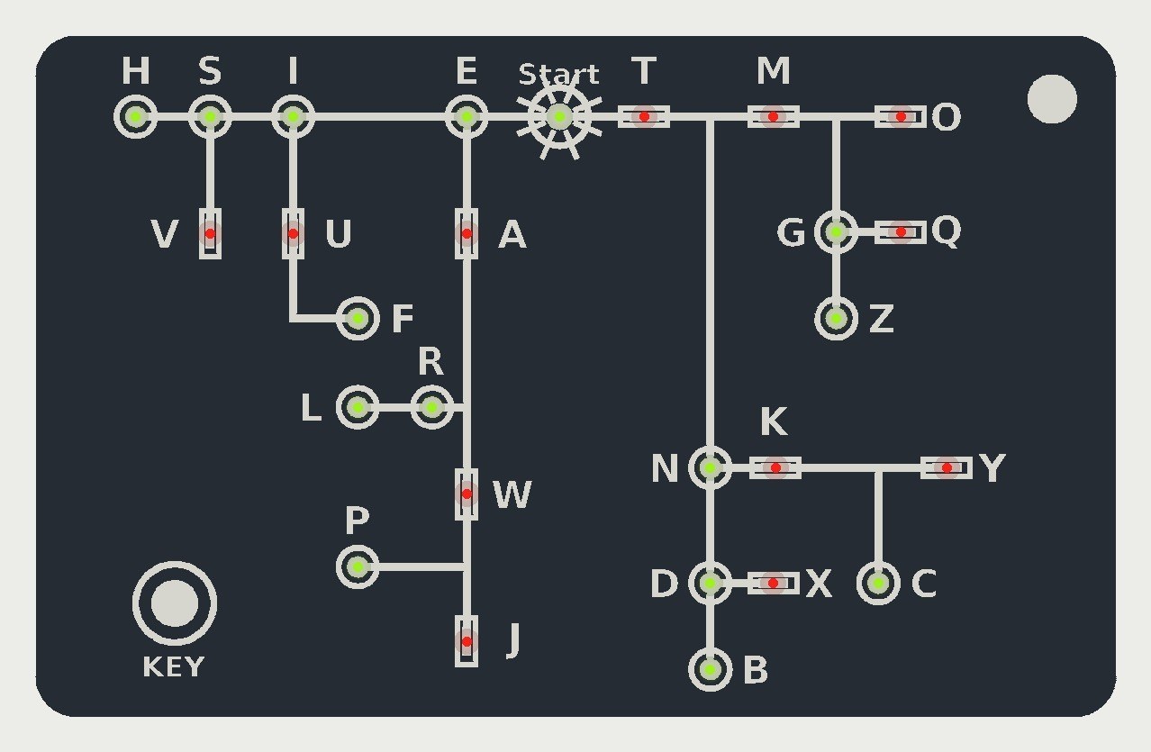
The pocket Morse decoder with no circuit board to order. A 3D-printed card the size of a bank card carries Dave Nathanson's decoding chart engraved in its face, with an SMD LED behind a window at every letter. Press the key short for a dot and long for a dash, and the letter you have reached lights.
Everything inside is hand-wired with enamelled copper wire to an Arduino Pro Mini, running on one CR2032 coin cell. The design has not been built yet.
Lanjutan
About 1 day, plus printing
Arahan
1
1
LED current and keying speed
LED current and keying speed
Memuatkan buku nota Jupyter…
2
2
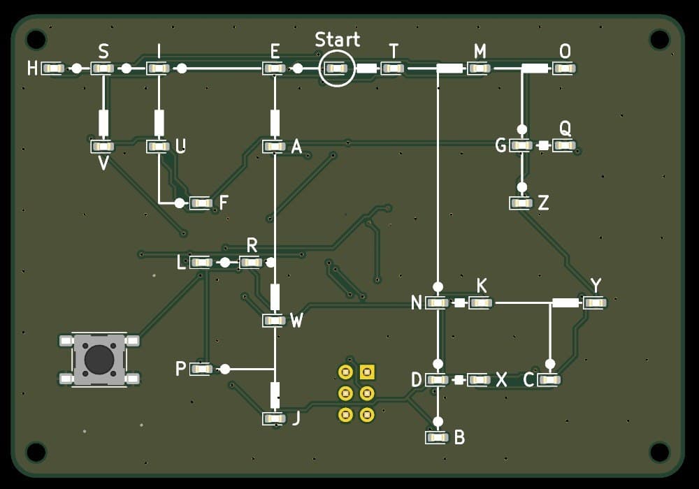
The same decoder on a circuit board
The same decoder on a circuit board
That version needs a board made to order. This one is printed and wired by hand.
3
3
Read the chart
Read the chart
Dave Nathanson (KG6ZJO) drew his decoding chart in 2010: "Start with your finger at "Start Here". Then move your finger to track the Morse dots & dashes. You will arrive at the correct letter!" On this card the LEDs do the tracking: yellow-green at the dots, red at the dashes.
4
4
Print the card body
Print the card body
The card, 85.6 x 54 x 7.5 mm, with the chart engraved 0.5 mm deep, a window and LED pocket at each letter, the key hole, four screw bosses and the key-ring hole. Print it face down on a smooth bed: PLA, 0.12 mm layers, no supports.
5
5
Print the lid
Print the lid
The 1.2 mm back lid with four countersunk screw holes and the credit and instructions engraved. PLA, 0.12 mm layers, engraved side down.
6
6
Fit the LEDs
Fit the LEDs
Press a 1206 LED into each pocket from the back, lens towards the window: yellow-green at the 14 dot rings and at Start, red at the 12 dash marks. Note each LED's cathode mark, then fix it with a tiny drop of glue at its edge, keeping the pads clean.
Bahan untuk langkah ini:
 LED cip27 keping
 Gam segera (sianoakrilat)1 keping
Alatan diperlukan:
 Penyepit berhujung tirus
 Kanta Pembesar
 Multimeter
7
7
Wiring table
Wiring table
The 27 LEDs share six lines, D3 to D8, each LED between two of them. Wire each LED's + (anode) and - (cathode) pad to the lines below; the firmware expects exactly this.
| LED | Code | Colour | + (anode) to | - (cathode) to |
|---|---|---|---|---|
| Start | (none) | yellow-green | D3 | D4 |
| T | - | red | D4 | D3 |
| E | . | yellow-green | D4 | D5 |
| M | -- | red | D5 | D4 |
| N | -. | yellow-green | D5 | D6 |
| A | .- | red | D6 | D5 |
| I | .. | yellow-green | D6 | D7 |
| O | --- | red | D7 | D6 |
| G | --. | yellow-green | D7 | D8 |
| K | -.- | red | D8 | D7 |
| D | -.. | yellow-green | D3 | D5 |
| W | .-- | red | D4 | D6 |
| R | .-. | yellow-green | D5 | D3 |
| U | ..- | red | D5 | D7 |
| S | ... | yellow-green | D6 | D4 |
| Q | --.- | red | D6 | D8 |
| Z | --.. | yellow-green | D7 | D5 |
| Y | -.-- | red | D8 | D6 |
| C | -.-. | yellow-green | D3 | D6 |
| X | -..- | red | D4 | D7 |
| B | -... | yellow-green | D5 | D8 |
| J | .--- | red | D6 | D3 |
| P | .--. | yellow-green | D7 | D4 |
| L | .-.. | yellow-green | D8 | D5 |
| F | ..-. | yellow-green | D3 | D7 |
| V | ...- | red | D4 | D8 |
| H | .... | yellow-green | D7 | D3 |
8
8
Wire the card
Wire the card
Remove the Pro Mini's power LED. Solder a 150 Ω resistor to each of D3-D8 and run a 0.2 mm solderable enamelled wire from each resistor round the cavity as that line's bus. Solder short wires from every LED pad to its bus, as the wiring table says; the iron strips the enamel. Wire the key between D2 and GND, and the cell holder's + to VCC and - to GND. Check every LED with the meter's diode test.
Bahan untuk langkah ini:
 Papan mikropengawal1 keping
 Rintangan6 keping
 Butang tekan1 keping
 Pemegang bateri1 keping
 Dawai Kuprum Bersalut Enamel1 keping
 Dawai Pateri1 keping
Alatan diperlukan:
 Alat pematerianPenyepit berhujung tirus
 FluksKanta PembesarMultimeter
9
9
The firmware
The firmware
morse_card.ino: every timing is a named constant at the top. Board in the Arduino IDE: Arduino Pro or Pro Mini, ATmega328P (3.3V, 8 MHz).
morse_card.inoarduino
10
10
Upload
Upload
Take the cell out. Connect a 3.3 V USB-to-serial adapter to the Pro Mini's programming pins, choose Arduino Pro or Pro Mini, ATmega328P (3.3V, 8 MHz), and upload. Start lights; key E (one short press) and E lights.
Alatan diperlukan:
 Penyesuai USB ke bersiri
 Komputer dengan Arduino IDE
11
11
Close the card
Close the card
Glue the key into its hole, plunger through the face. Stick the Pro Mini and the cell holder to the lid's inside with double-sided tape, leaving the wires some slack, put a CR2032 in, and screw the lid on with four M2 x 6 self-tapping screws.
Bahan untuk langkah ini:
Gam segera (sianoakrilat)1 keping Pita pelekat dua muka1 keping
 Skru tap sendiri4 keping
 Bateri syiling CR20321 keping
 Filamen PLA1 keping
Alatan diperlukan:
 Pencetak 3D filamen (FDM)
 Set pemutar skru jitu
12
12
The build in 3D
The build in 3D
FreeCAD model of the card: the body with its engraved chart and LED windows, the lid, and the space taken by the Pro Mini, cell holder, key and screws, checked for clashes.
13
13
Troubleshooting
Troubleshooting
Printed Morse card troubleshooting.
Flow
Loading...
14
14
History and honest limits
History and honest limits
The chart is **Dave Nathanson**'s (KG6ZJO), drawn in 2010 and shared as copyleft. The letter codes are ITU-R M.1677-1's. The card, its sizes, parts, wiring and timings are ours. The model was checked for clashes and the firmware compiles with all 26 codes checked against ITU, but the card has not been printed, wired or tested.
Bahan
12- 27 kepingPemegang Tempat
- 2 kepingPemegang Tempat
- 1 kepingPemegang Tempat
- 6 kepingPemegang Tempat
- Pemegang Tempat
- Pemegang Tempat
- 1 kepingPemegang Tempat
- 1 kepingPemegang Tempat
- 1 kepingPemegang Tempat
- 4 kepingPemegang Tempat
- 1 kepingPemegang Tempat
- 1 kepingPemegang Tempat
Alatan Diperlukan
9- Pemegang Tempat
- Pemegang Tempat
- Pemegang Tempat
- 2 vendors sell this, none ship to you yetPemegang Tempat
- Pemegang Tempat
- 3 vendors sell this, none ship to you yetPemegang Tempat
- Pemegang Tempat
- Pemegang Tempat
- Pemegang Tempat
Fail reka bentuk
3Blueprint ini membuat
Blueprint berkaitan
Blueprint ini berkongsi pengetahuan — teknik, bahan atau prinsip

CC0 Domain Awam
Blueprint ini dikeluarkan di bawah CC0. Anda bebas menyalin, mengubah, mengedar, dan menggunakan karya ini untuk sebarang tujuan, tanpa meminta kebenaran.
Sokong Pembuat dengan membeli produk melalui Blueprint mereka di mana mereka memperoleh Komisen Pembuat ditetapkan oleh Penjual, atau cipta iterasi baru Blueprint ini dan sertakan ia sebagai sambungan dalam Blueprint anda sendiri untuk berkongsi hasil.