IṢẸ́ ỌNÀ
ẸWÀ ÀTI ÌLERA
IṢẸ́ ỌWỌ́
ÀṢÀ ÀTI ÌTÀN
ÌṢERÉ
ÀYÍKÁ
OÚNJẸ ÀTI OHUN MÍMU
REVERSE ENGINEERING
SÁYẸ́ǸSÌ
ERÉ ÌDÁRAYÁ
ÌMỌ̀-Ẹ̀RỌ
ÀWỌN OHUN WÍWỌ̀
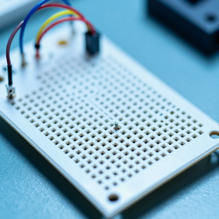


Breadboarding: How It Connects, and When It Lies to You
A breadboard is a grid of spring clips in a plastic block. Understanding which holes are joined to which takes about a minute, and every SIK circuit published here is built on one.
What takes longer to learn is that the breadboard is not a neutral place to test a circuit. It adds resistance at every contact, capacitance between every adjacent strip, and inductance along every jumper — so a circuit can work perfectly on a breadboard and fail when soldered, or much more often, fail on the breadboard and work fine soldered.
Knowing which faults are yours and which belong to the board is the difference between debugging your circuit and debugging the furniture.
Olùbẹ̀rẹ̀
2 hours
Ìlànà
1
1
Rows across, rails along, and a gap down the middle
Rows across, rails along, and a gap down the middle
In the main field, each row of five holes is connected together, across the board. The rows are NOT connected to each other. Down the long edges the power rails run the other way — along the board — and are usually marked with a red and a blue line.
The channel down the centre separates the left half from the right half. That gap exists so a chip can straddle it with each leg landing in its own private five-hole row; without it, opposite legs would be shorted together.
Prove it rather than trusting the description: put the meter on continuity and walk it around one row, then across to the next, then along a rail. Two minutes with the meter replaces any diagram.
Àwọn irinṣẹ́ tí a nílò:
 Pátákó Àdánwò
 Òǹwọ̀n iná mànàmáná onírúurú
2
2
The rails are often split, and that is the classic beginner fault
The rails are often split, and that is the classic beginner fault
On many boards the power rails are broken in the middle — there is a small gap in the printed line where the strip underneath stops and a new one starts. The top half and the bottom half of the same rail are not connected.
This produces the most frustrating breadboard fault there is: half the circuit works and the other half is dead, everything looks correct, and the wiring is correct. Bridge the halves with a short jumper at the gap and it comes alive.
Check yours with the continuity beeper the first time you use it, and if the rails are split, get into the habit of bridging both rails as the very first thing you do on a new build.
Àwọn irinṣẹ́ tí a nílò:
Pátákó ÀdánwòÒǹwọ̀n iná mànàmáná onírúurú Okùn Ìsopọ̀
3
3
What the board adds to your circuit
What the board adds to your circuit
Ń ṣí ìwé Jupyter…
Àwọn irinṣẹ́ tí a nílò:
Pátákó Àdánwò Ẹ̀rọ Ìṣirò
4
4
Wire discipline: short, flat, and colour-coded
Wire discipline: short, flat, and colour-coded
Cut jumpers to length and lay them flat on the board rather than using long pre-made leads that arch over everything. Keep red for the positive rail and black for ground, always.
A flat, short layout is not tidiness for its own sake. You can trace it with a finger, you can see which row a wire enters, and you can lift one component without disturbing six others. A bird's nest hides exactly the fault you are looking for.
Never push solid wire thicker than about 0.6 mm into a hole, and never push in stranded wire at all. Thick wire permanently stretches the clip, and from then on that hole is an intermittent contact for every circuit you ever build there — the fault that appears and disappears when you touch the board.
Àwọn irinṣẹ́ tí a nílò:
Pátákó ÀdánwòOkùn Ìsopọ̀ Ẹ̀mú ìbóhun
 Ohun ìgé okùn waya
5
5
Build it in stages and test as you go
Build it in stages and test as you go
Wire the power rails and check the voltage before adding a single component. Then build one functional block, test it, and only then add the next.
A circuit built entirely and then powered for the first time gives you one fact — it does not work — and a whole board to search. Built in four stages, the fault is in the stage you just added, which is a search of about five components.
This is the cheapest debugging technique in electronics and it costs nothing but the discipline to not wire the whole thing at once. The fault-finding rung that follows is what you do when you did build it all at once anyway.
Àwọn ohun èlò fún ìgbésẹ̀ yìí:
 Ìṣù LED1 ẹyọ
 Àkójọ Rẹsístà1 ẹyọ
Àwọn irinṣẹ́ tí a nílò:
Pátákó ÀdánwòÒǹwọ̀n iná mànàmáná onírúurú Ìpèsè Agbára Tábìlì
Àwọn ohun-èlò
2- 1 ẹyọÀyè
- láti$5.64
Blueprint tó jọra
Àwọn blueprint wọ̀nyí pín ìmọ̀ — ọ̀nà, ohun-èlò tàbí ìlànà
CC0 Àgbègbè Gbogbogbò
Blueprint yìí ti jáde lábẹ́ CC0. O lè ṣe àdàkọ, yí padà, pín, àti lò láìsí ìyọ̀ǹda.
Ṣàtìlẹ́yìn Olùṣẹ́dá nípa rírà àwọn ọjà nipasẹ̀ Blueprint wọn Ẹ̀san Olùṣẹ́dá tí àwọn Olùtajà gbé kalẹ̀, tàbí ṣẹ̀dá àtúnṣe tuntun ti Blueprint yìí kí o sì fi sínú Blueprint rẹ gẹ́gẹ́ bí ìsopọ̀ láti pín owó-wíwọlé.