कला
सुन्दरता र कल्याण
हस्तकला
संस्कृति र इतिहास
मनोरञ्जन
वातावरण
खाना र पेय
हरित भविष्य
रिभर्स इन्जिनियरिङ
विज्ञान
खेलकुद
प्रविधि
पहिर्न मिल्ने
अनुवादित
BLUEPRINT NFT

झलमलाउँदै LED — तपाईंको पहिलो Arduino परियोजना
क्लासिक पहिलो इलेक्ट्रोनिक्स परियोजना! Arduino, ब्रेडबोर्ड, प्रतिरोधक, र एकल LED को उपयोग गरेर झलमलाउँदै LED सर्किट बनाउनुहोस्। बिल्कुल शुरुवातीहरूको लागि परिपूर्ण — कुनै सोल्डरिङ आवश्यक छैन।
निर्देशनहरू
1
1
आपके घटकहरू जमा गर्नुहोस्
आपके घटकहरू जमा गर्नुहोस्
तलको सूचीबद्ध सभी घटकहरू सংग्रह गर्नुहोस्। कुनै焊接को आवश्यकता छैन — सबै कुरा ब्रेडबोर्डमा प्लग हुन्छ।
Materials for this step:
 SparkFun Inventor's Kit - V3.21 किट
Arduino Uno R31 टुक्रा
5mm LED (any color)1 टुक्रा
 220 ohm Resistor (1/4W)1 टुक्रा
Breadboard1 टुक्रा
Jumper Wires (Male-to-Male)2 टुक्रा
USB-B Cable1 टुक्रा
Tools needed:
Computer with Arduino IDE
2
2
सर्किट योजनाबद्ध
सर्किट योजनाबद्ध
सिग्नल Arduino Pin 13 → 220Ω प्रतिरोधक (R1) → LED (D1) → GND बाट प्रवाह हुन्छ। प्रतिरोधकले LED को सुरक्षा गर्न करेन्ट सीमित गर्छ।
Materials for this step:
Arduino Uno R31 टुक्रा
5mm LED (any color)1 टुक्रा
220 ohm Resistor (1/4W)1 टुक्रा3
3
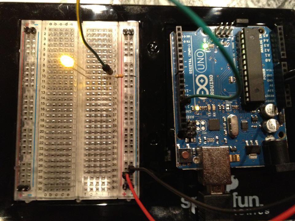
यसलाई वायर गर्नुहोस्
यसलाई वायर गर्नुहोस्
- LED लाई ब्रेडबोर्डमा घुसाउनुहोस् — लामो खुट्टा (anode +) एक पङ्क्तिमा, छोटो खुट्टा (cathode −) अर्कोमा।
- 220Ω resistor को एक खुट्टा LED cathode जस्तै पङ्क्तिमा घुसाउनुहोस्। अर्को खुट्टा अलग पङ्क्तिमा।
- Jumper wire LED anode पङ्क्तिबाट → Arduino Pin 13 सम्म।
- Jumper wire resistor खाली पङ्क्तिबाट → Arduino GND सम्म।
Materials for this step:
5mm LED (any color)1 टुक्रा
220 ohm Resistor (1/4W)1 टुक्राBreadboard1 टुक्रा
Jumper Wires (Male-to-Male)2 टुक्रा
4
4
Blink कोड अपलोड गर्नुहोस्
Blink कोड अपलोड गर्नुहोस्
USB मार्फत Arduino जडान गर्नुहोस्। Arduino IDE खोल्नुहोस्, Tools → Board → Arduino Uno चयन गर्नुहोस्, कोड पेस्ट गर्नुहोस् र Upload मा क्लिक गर्नुहोस्।
blink.inoarduino
Materials for this step:
Arduino Uno R31 टुक्रा
USB-B Cable1 टुक्रा
Tools needed:
Computer with Arduino IDE
5
5
PCB लेआउट (संदर्भ)
PCB लेआउट (संदर्भ)
यसले सर्किटलाई PCB लेआउटको रूपमा देखाउँछ। यस प्रकल्पको लागि आवश्यक छैन — ब्रेडबोर्ड पूर्णतया काम गर्छ — तर यसले देखाउँछ कि एउटा वास्तविक बोर्डको रूपमा निर्मित गरिएको भए एउटै सर्किट कस्तो देखिन्थ्यो।
6
6
परीक्षण र प्रयोग
परीक्षण र प्रयोग
LED झिमझिमिएको छ? बधाई छ! तपाईंले भर्खास्ट प्रोग्राम गर्नु भएको छ।
समस्या समाधान:
अगलो प्रयोगहरु:
समस्या समाधान:
- LED उज्ज्वल हुन सकेको छैन? LED पलट गर्नुहोस् — लामो खुट्टा Pin 13 तर्फ।
- LED सधैं अन छ? कोड सफलतापूर्वक अपलोड भएको जाँच गर्नुहोस्।
- केहि भएन? तार जोडिएको स्केमेटिक चरण २ सँग मेल खाँदो जाँच गर्नुहोस्।
अगलो प्रयोगहरु:
delay()मानहरु परिवर्तन गरी झिमझिमको गति नियन्त्रण गर्नुहोस्- Pin 12 मा दोस्रो LED जोड्नुहोस्
- RGB LED सँग बदल्नुहोस् (देख्नुहोस् SIK Circuit 3)
सामग्री
7- $105.00
- प्लेसहोल्डर
आवश्यक उपकरणहरू
2- Computer with Arduino IDE
- प्लेसहोल्डर
Estimated Total
$105.00Related blueprints
Other builds that share materials, tools, or techniques with this one.

Using a Shift Register — SIK Circuit 14electronics/active
Blinking an LED with LilyPad Arduinoelectronics

Making Charcoal — The First Chemical Processmaterials
The Spinning Jenny — Multi-Spindle Yarn Productiontextiles
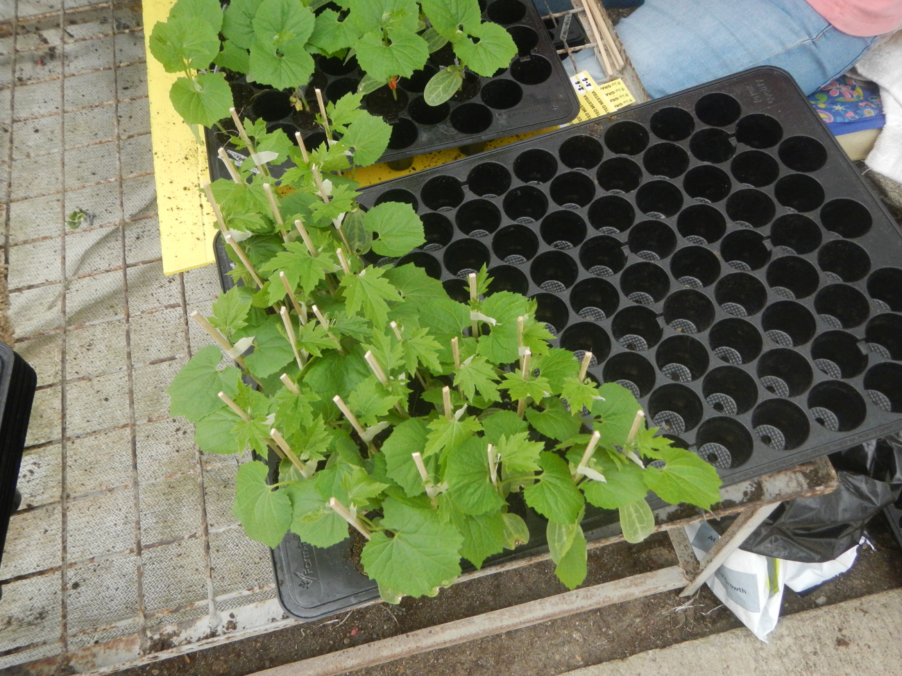
Starting Seeds Indoors — Raising Seedlings for a Head Start
Driving a Motor — SIK Circuit 12electronics/electromech
CC0 सार्वजनिक डोमेन
यो ब्लुप्रिन्ट CC0 अन्तर्गत जारी गरिएको छ। तपाईं अनुमति नसोधी प्रतिलिपि, परिमार्जन, वितरण र प्रयोग गर्न सक्नुहुन्छ।
ब्लुप्रिन्ट मार्फत उत्पादनहरू किनेर सिर्जनाकर्तालाई सहयोग गर्नुहोस् सिर्जनाकर्ता कमिसन विक्रेताले तोकेको, वा यो ब्लुप्रिन्टको नयाँ संस्करण बनाउनुहोस् र आम्दानी बाँड्न आफ्नो ब्लुप्रिन्टमा जडानको रूपमा समावेश गर्नुहोस्।