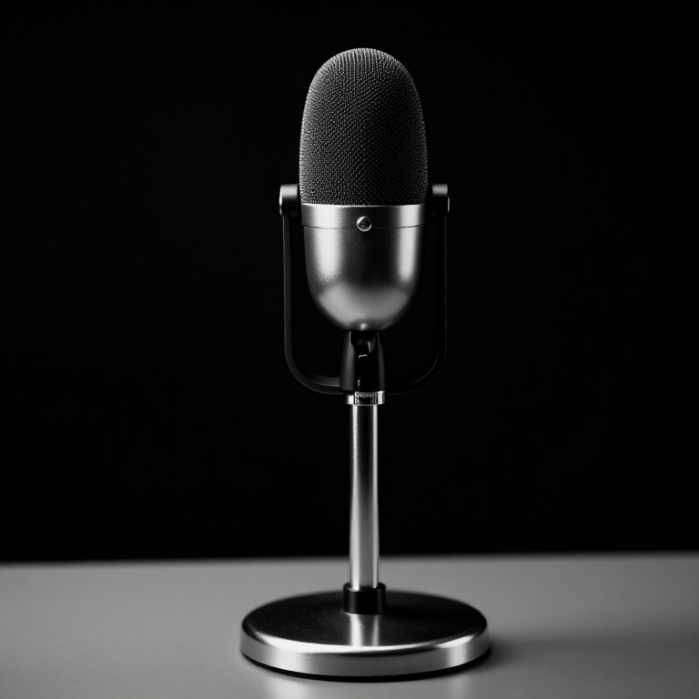


Ribbon Microphone
निर्देशनहरू
Corrugate a strip of very thin foil
Corrugate a strip of very thin foil
The corrugations are what let a stiff strip behave like a limp one.
- Cut a strip of the thinnest aluminium foil you can obtain, about 4 mm wide and 50 mm long.
- Lay it between two coarse-toothed gears or a corrugating jig and press gently to form transverse ripples.
- Handle it only with tweezers and a light touch — a fingerprint will tear it.
- Inspect for cracks along the corrugation crests.
A flat strip pulled taut is stiff and resonant; a corrugated one is compliant along its length. The ripples let the ribbon stretch and move as a whole without needing tension to hold it flat, so its resonance can be placed below the audible band. That is the trick that makes the ribbon work, and it is why every ribbon ever made is corrugated.
This is the most fragile component in this entire catalogue. Expect to destroy several before one survives, and never blow on a finished ribbon to test it.यस चरणका सामग्री:
 एल्युमिनियम पत्र1 रोल
चाहिने औजार:
 डिजिटल क्यालिपर ६ इन्च
 रेतीहरूको सेट
 संयुक्त गुनिया
Suspend it in a strong transverse field
Suspend it in a strong transverse field
The ribbon is a single-turn conductor, so it needs all the flux it can get.
- Mount two magnets facing each other with a gap of about 5 mm, poles opposed.
- Clamp the ribbon at top and bottom so it hangs centrally in the gap, with just enough slack to be limp.
- Ensure both faces are open to the air.
- Connect a lead to each clamp.
The output impedance here is a fraction of an ohm, because the ribbon is one turn of aluminium. The voltage generated is correspondingly tiny — far smaller than a moving coil with forty turns. This is why every ribbon microphone has a step-up transformer built into its body, and why an early ribbon connected directly to an input produced almost nothing.
Both faces open is the defining requirement. Enclose the back and you have converted it into a pressure microphone and thrown away the figure-of-eight pattern that is the ribbon's whole character.यस चरणका सामग्री:
 फेराइट मणिको सेट1 किट
 इनामेल लगाइएको तामाको तार1 रोल
 पित्तलको गोलो डण्डी1 टुक्रा
चाहिने औजार:
 प्रयोगशाला स्तरको डिजिटल बहुमापकडिजिटल क्यालिपर ६ इन्चरेतीहरूको सेट
 बेन्चको भाइस
Add the step-up transformer
Add the step-up transformer
Without it the signal is unusable; with it the ribbon becomes a practical microphone.
- Wind or obtain a transformer with a very low impedance primary and a high impedance secondary.
- Connect the ribbon to the primary and take the output from the secondary.
- Measure the signal before and after the transformer with the oscilloscope.
- Note the ratio.
The transformer is doing impedance matching, not just amplification. It converts a very low voltage at very low impedance into a usable voltage at an impedance a preamplifier can work with. No energy is created — the transformer trades current for voltage — but without that trade the ribbon's output is buried in the noise of whatever follows it.
Transformers are also why vintage ribbons sound the way they do. The transformer's own frequency response and saturation behaviour are part of the microphone's character, not an imperfection to be designed out.यस चरणका सामग्री:
इनामेल लगाइएको तामाको तार1 रोलफेराइट मणिको सेट1 किटचाहिने औजार:
 डिजिटल तरङ्गदर्शीप्रयोगशाला स्तरको डिजिटल बहुमापकडिजिटल क्यालिपर ६ इन्च
Plot the figure-of-eight and find the null
Plot the figure-of-eight and find the null
The pattern comes free with the physics — verify it and then use it.
- Set a steady tone playing and walk it in a circle around the microphone at constant distance.
- Record the output every 15 degrees and plot it as a polar diagram.
- Find the angles of deepest rejection.
- Now place an unwanted noise source exactly at a null and a wanted source at the front.
यस चरणका सामग्री:
 रेखाचित्र कागज1 pad
चाहिने औजार:
 DDS संकेत जेनेरेटरडिजिटल तरङ्गदर्शीप्रयोगशाला स्तरको डिजिटल बहुमापकसंयुक्त गुनिया
Velocity instead of pressure, and history
Velocity instead of pressure, and history
The ribbon microphone was developed in the early 1920s — Walter Schottky and Erwin Gerlach in Germany, and independently Harry Olson at RCA, whose 44 and 77 series became the defining broadcast microphones of the 1930s and 40s. The RCA 44 hanging in front of a big band is one of the most recognisable objects of the era.
Its pattern turned out to matter enormously. Alan Blumlein, whose stereo work is next in this batch, used crossed figure-of-eight microphones to capture a stereo image — a technique impossible without a transducer that naturally produces that pattern. So the ribbon is not merely a microphone in this chain; it is the enabling component for stereo recording.
Its acoustic character has a physical explanation. The ribbon's moving mass is a fraction of a moving coil's, so it follows sudden transients without overshoot, and its high-frequency response falls away gently rather than peaking. Both together produce the smooth, unaggressive sound ribbons are prized for — and both are consequences of a two-micron foil rather than of any deliberate voicing.
Its honest limits are severe: the ribbon can be destroyed by a gust of wind, by phantom power applied to the wrong pins, or by being carried face-first into a draught. Output is very low. And the figure-of-eight picks up the room behind it as much as the source in front, which is wonderful in a good room and unusable in a bad one.
सामग्री
5- 1 रोलप्लेसहोल्डर
- 1 किटप्लेसहोल्डर
- प्लेसहोल्डर
- 1 टुक्राप्लेसहोल्डर
- 1 padप्लेसहोल्डर
आवश्यक उपकरणहरू
7- प्लेसहोल्डर
- प्लेसहोल्डर
- प्लेसहोल्डर
- प्लेसहोल्डर
- प्लेसहोल्डर
- 1 vendor sell this, none ship to you yetप्लेसहोल्डर
- प्लेसहोल्डर
सम्बन्धित ब्लुप्रिन्ट
यी ब्लुप्रिन्टहरूले ज्ञान साझा गर्छन् — प्रविधि, सामग्री वा सिद्धान्त

CC0 सार्वजनिक डोमेन
यो ब्लुप्रिन्ट CC0 अन्तर्गत जारी गरिएको छ। तपाईं अनुमति नसोधी प्रतिलिपि, परिमार्जन, वितरण र प्रयोग गर्न सक्नुहुन्छ।
ब्लुप्रिन्ट मार्फत उत्पादनहरू किनेर सिर्जनाकर्तालाई सहयोग गर्नुहोस् सिर्जनाकर्ता कमिसन विक्रेताले तोकेको, वा यो ब्लुप्रिन्टको नयाँ संस्करण बनाउनुहोस् र आम्दानी बाँड्न आफ्नो ब्लुप्रिन्टमा जडानको रूपमा समावेश गर्नुहोस्।