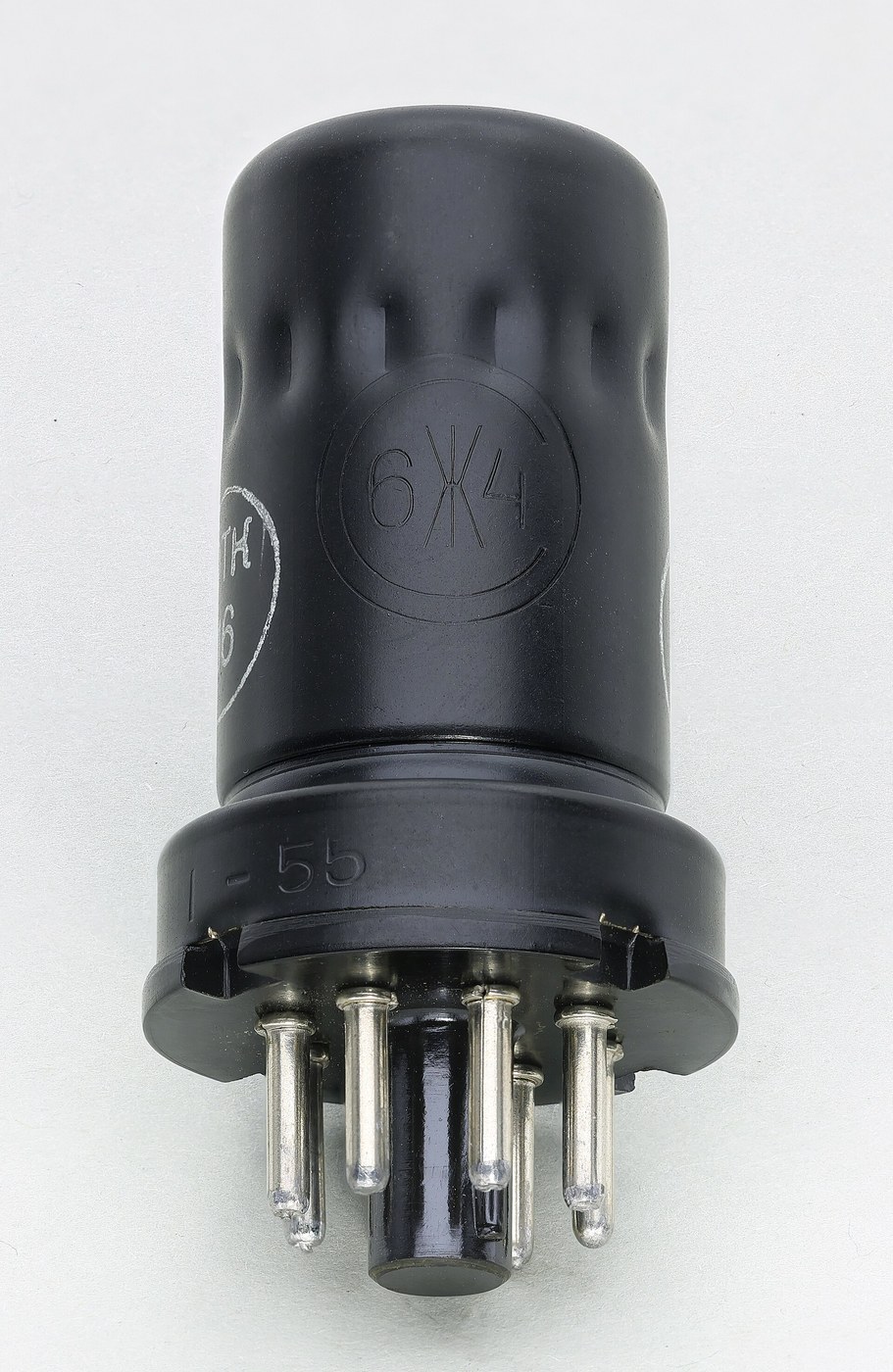


The Screen Grid and the Pentode
निर्देशनहरू
Measure the capacitance that causes the trouble
Measure the capacitance that causes the trouble
Find the offending component, which is not a component at all.
- With a triode valve out of circuit and cold, measure the capacitance between anode and grid with an LCR meter.
- Record it — it will be a few picofarads.
- Now compute what that capacitance appears as at the input, multiplied by the stage gain plus one.
A few picofarads of anode-grid capacitance behaves like tens or hundreds of picofarads across the input, because the anode swings in the opposite direction to the grid and by a much larger amount. This multiplication is the Miller effect, and it means the input capacitance of an amplifier depends on its own gain.
Two consequences follow immediately, and both were serious. The huge effective input capacitance detunes and damps the tuned circuit feeding the stage. And because the feedback path exists at all, with the right phase shift the stage will oscillate on its own.
Neutralisation was the pre-1926 workaround: deliberately feed back an equal and opposite signal through a small adjustable capacitor to cancel the unwanted path. It works, and it must be re-trimmed for every valve, every frequency and every replacement. That fragility is what made the screen grid worth inventing.यस चरणका सामग्री:
 ट्रायोड भल्भ1 सेट
 भल्भ सकेट1 सेट
 क्यापासिटर किट1 किट
चाहिने औजार:
 टेबल LCR मिटर
 प्रयोगशाला स्तरको डिजिटल बहुमापक
 डिजिटल क्यालिपर ६ इन्च
 सफा सुरक्षा चस्मा
Add a screen grid and shield the anode from the grid
Add a screen grid and shield the anode from the grid
Fit a tetrode and repeat every measurement.
- Build the same amplifier stage using a tetrode, with the screen grid connected to a steady positive supply and bypassed to earth by a good capacitor.
- Measure anode-to-control-grid capacitance again.
- Measure the stage gain.
- Try to make it oscillate by increasing the load impedance.
Anode-grid capacitance falls by a factor of hundreds, gain rises by a factor of tens, and the stage is far harder to provoke into oscillating. The screen is doing two jobs at once: electrostatically it is an earthed shield between the two electrodes, and electrically it accelerates electrons past the control grid so the anode voltage barely influences the current at all.
The bypass capacitor is not optional. The screen must be at earth potential for signals even while sitting at a high DC voltage. Leave it unbypassed and the screen swings with the signal, the shielding evaporates, and you have an expensive triode.
This is a genuinely elegant kind of fix — the problem was geometric, so the solution is a piece of geometry rather than a compensating circuit. Compare it with neutralisation, which cancels a fault rather than removing it, and note which one survived.यस चरणका सामग्री:
 टेट्रोड भल्भ1 सेटभल्भ सकेट1 सेटक्यापासिटर किट1 किट
 प्रतिरोधकको सेट1 किट
 प्वाल भएको बोर्ड / नमुना बोर्ड1 टुक्रा
 ६३/३७ रेजिन-कोर टाँकाको तार1 reel
चाहिने औजार:
टेबल LCR मिटर तरङ्गदर्शी
 संकेत जेनेरेटरप्रयोगशाला स्तरको डिजिटल बहुमापक
 मिलाउन सकिने टेबुल विद्युत् आपूर्ति
 टाँक लगाउने स्टेसनसफा सुरक्षा चस्मा
Find the kink, where the tetrode misbehaves
Find the kink, where the tetrode misbehaves
The tetrode introduced a new fault, and its shape on the curve tells you exactly what it is.
- Plot anode current against anode voltage at a fixed control-grid voltage, sweeping the anode from zero upward.
- Pay close attention to the region where anode voltage is below the screen voltage.
- Mark any region where current FALLS as voltage RISES.
There is a dip — a region of negative resistance — where increasing the anode voltage decreases the anode current. The cause is secondary emission: electrons arrive at the anode fast enough to knock further electrons out of its surface, and while the anode is at a lower potential than the screen, those knocked-out electrons are collected by the SCREEN instead of returning. Current that should have gone to the anode goes to the screen, so anode current falls.
A negative-resistance region is not merely untidy. It can sustain oscillation on its own — the dynatron oscillator was built deliberately on this effect — and it badly distorts an amplifier whose signal swings into that region.
So the tetrode traded one instability for another. Worth noting as a pattern: a fix that introduces a new mechanism usually introduces a new failure mode with it, and the second one is often discovered later and in service.यस चरणका सामग्री:
प्रतिरोधकको सेट1 किट रेखाचित्र कागज1 pad
चाहिने औजार:
तरङ्गदर्शीप्रयोगशाला स्तरको डिजिटल बहुमापकमिलाउन सकिने टेबुल विद्युत् आपूर्तिसंकेत जेनेरेटरसफा सुरक्षा चस्माAdd a suppressor grid and get the pentode
Add a suppressor grid and get the pentode
Fix the secondary-emission problem with a third grid, and understand why it is at earth.
- Build the same stage with a pentode, its suppressor grid connected to the cathode.
- Repeat the anode current against anode voltage sweep.
- Compare the curve with the tetrode’s.
The kink is gone; the curve rises and then flattens into a long horizontal plateau. The suppressor sits between screen and anode at cathode potential — negative relative to both — so it repels the slow secondary electrons knocked out of the anode and returns them to the anode, while the fast primary electrons from the cathode sail straight through.
The flat plateau is worth dwelling on: anode current is now almost independent of anode voltage. That is very nearly a constant-current source controlled by the grid, which is exactly what an amplifier wants — enormous voltage gain, and a stage whose behaviour barely depends on its load.
Reverse-engineering note: the beam tetrode reaches the same result differently, using beam-forming plates to create a dense space charge between screen and anode that repels secondaries without a third grid. Two mechanisms, one goal — and both are still in production for audio amplifiers, where their different distortion characters are argued over to this day.यस चरणका सामग्री:
 पेन्टोड भल्भ1 सेटभल्भ सकेट1 सेटप्रतिरोधकको सेट1 किटक्यापासिटर किट1 किटरेखाचित्र कागज1 pad
चाहिने औजार:
तरङ्गदर्शीप्रयोगशाला स्तरको डिजिटल बहुमापकमिलाउन सकिने टेबुल विद्युत् आपूर्तिसंकेत जेनेरेटरटाँक लगाउने स्टेसनसफा सुरक्षा चस्माBuild a stable RF amplifier and prove the point
Build a stable RF amplifier and prove the point
Put the pentode to work in the job the triode could not hold.
- Build a tuned RF amplifier stage using the pentode, with a high-Q tuned circuit as its anode load.
- Measure gain and check the tuned circuit’s Q with the stage running.
- Increase the load impedance progressively and see how far you can push gain before instability appears.
- Repeat the whole test with a triode in an equivalent circuit.
The pentode gives far more gain before oscillating, and it loads the tuned circuit far less, so selectivity survives. That combination is what made multi-stage IF strips practical — and therefore what made the superheterodyne buildable as a mass-market product rather than a laboratory curiosity.
Layout matters more than the schematic here. At radio frequencies a centimetre of wire is an inductor and two parallel wires are a capacitor, so a screen-grid valve carefully shielded internally can still oscillate if input and output wiring run side by side on the board. The metal cans, chassis partitions and short direct leads in old radios are not tidiness — they are the parts of the circuit that do not appear on the diagram.यस चरणका सामग्री:
 इनामेल लगाइएको तामाको तार10 mक्यापासिटर किट1 किटप्रतिरोधकको सेट1 किट
 एल्युमिनियमको पाता1 पाना
चाहिने औजार:
तरङ्गदर्शीसंकेत जेनेरेटर स्पेक्ट्रम विश्लेषक / FFT सफ्टवेयरटेबल LCR मिटरप्रयोगशाला स्तरको डिजिटल बहुमापकमिलाउन सकिने टेबुल विद्युत् आपूर्तिटाँक लगाउने स्टेसन
 रेतीहरूको सेटसफा सुरक्षा चस्मा
सामग्री
11- 1 सेटप्लेसहोल्डर
- 1 सेटप्लेसहोल्डर
- 1 किटप्लेसहोल्डर
- 1 सेटप्लेसहोल्डर
- प्लेसहोल्डर
- 1 टुक्राप्लेसहोल्डर
- प्लेसहोल्डर
- 1 padप्लेसहोल्डर
- 1 सेटप्लेसहोल्डर
- प्लेसहोल्डर
- 1 पानाप्लेसहोल्डर
आवश्यक उपकरणहरू
10- प्लेसहोल्डर
- प्लेसहोल्डर
- प्लेसहोल्डर
- प्लेसहोल्डर
- प्लेसहोल्डर
- प्लेसहोल्डर
- प्लेसहोल्डर
- प्लेसहोल्डर
- प्लेसहोल्डर
- प्लेसहोल्डर
सम्बन्धित ब्लुप्रिन्ट
यी ब्लुप्रिन्टहरूले ज्ञान साझा गर्छन् — प्रविधि, सामग्री वा सिद्धान्त


CC0 सार्वजनिक डोमेन
यो ब्लुप्रिन्ट CC0 अन्तर्गत जारी गरिएको छ। तपाईं अनुमति नसोधी प्रतिलिपि, परिमार्जन, वितरण र प्रयोग गर्न सक्नुहुन्छ।
ब्लुप्रिन्ट मार्फत उत्पादनहरू किनेर सिर्जनाकर्तालाई सहयोग गर्नुहोस् सिर्जनाकर्ता कमिसन विक्रेताले तोकेको, वा यो ब्लुप्रिन्टको नयाँ संस्करण बनाउनुहोस् र आम्दानी बाँड्न आफ्नो ब्लुप्रिन्टमा जडानको रूपमा समावेश गर्नुहोस्।