कला
सुन्दरता र कल्याण
हस्तकला
संस्कृति र इतिहास
मनोरञ्जन
वातावरण
खाना र पेय
रिभर्स इन्जिनियरिङ
विज्ञान
खेलकुद
प्रविधि
पहिर्न मिल्ने
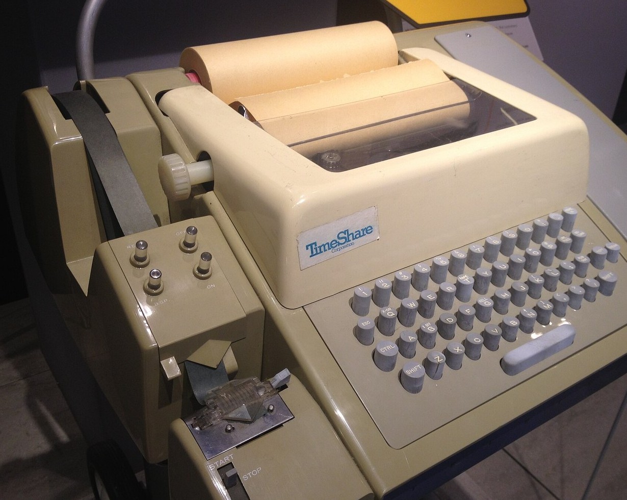


The UART and Start-Stop Framing
Two machines, one wire, and no shared clock. That is the whole problem, and everything else in this batch is built on the answer to it.
A human telegraphist needed no convention: Morse has rhythm, and a listener locks onto it without being told. A machine has an oscillator that is a percent or two off, drifting with temperature, and it cannot hear rhythm. It needs to be told exactly when a character starts.
The answer came from teleprinters and it is almost embarrassingly simple. Hold the line at MARK when idle. Drop it to SPACE for exactly one bit time — that is the start bit, and its falling edge is the only timing reference in the entire system. Send the data bits, least significant first. Then return to MARK for at least one bit time, the stop bit, so the line is guaranteed back at idle and the next falling edge is unambiguous.
It costs two bits in every ten, a flat twenty percent, and it buys a clock tolerance of about five percent split between the two ends — which a cheap RC oscillator can hold. That trade is the whole design. Resynchronise often and you may use a bad clock; resynchronise rarely and you need a crystal, which is the road that leads to Ethernet's preamble seven blueprints later.
FULLY BUILDABLE. Bit-bang a frame, look at it on a scope, then walk the receiver's baud rate off by a percent at a time and find where it breaks. The stop bit fails before the data does, every time, and that is not a coincidence — it is the last bit sampled and it carries the most accumulated error.
शुरुआती
3 hours
निर्देशनहरू
1
1
Where the framing came from
Where the framing came from
Work the Baudot blueprint first. It gives you the fixed-length character code — five bits, always five, unlike Morse's variable lengths — that makes machine reception possible at all.
What Baudot does NOT settle is when a character begins. A teleprinter's mechanism solved it with a start pulse that released a rotating distributor and a longer stop pulse that let it come to rest, which is where the odd 1.5-bit stop length comes from.
The UART is that mechanism in silicon: same start bit, same idle-at-mark, same least-significant-bit-first order. Nothing was invented. It was electrified.
2
2
Bit-bang a frame and break it deliberately
Bit-bang a frame and break it deliberately
Join GPIO17 to GPIO16 with one jumper and flash the sketch. GPIO17 is the ESP32's hardware UART transmitting at 9600 baud; GPIO16 is a receiver written in software, whose baud rate the sketch walks from ten percent slow to ten percent fast. Put the scope on GPIO17 first and send 0x55: alternating bits give the clearest possible picture of the frame, and you can measure one bit time directly with the cursors.
Then let the sweep run. At each step it counts how many bytes arrived correctly, how many raised a FRAMING error, how many arrived as the wrong value, and how many never arrived. The receiver samples every bit at (0.5 + k) of its own bit time after the start edge, so the error accumulates and the stop bit is the first sample to land in the wrong place, at a little over 5 %. Which symptom that produces depends on the direction. Receiver FAST: the stop sample lands on the last data bit, and whenever that bit is 0 you get a framing error, before any wrong data. Receiver SLOW: the stop sample lands late, on the idle mark between bytes, which is high, so it passes; the first failures are wrong data instead.
An exact model of the sample points, with the sketch's five bytes, predicts all five correct from -5 % to +5 %; at +6 % three framing errors (0x55, 0x00, 0x41, whose last data bit is 0); at -6 % three wrong bytes and no framing errors. The sketch was compiled for the ESP32 with the Arduino ESP32 core 3.3.12. An earlier version bit-banged the transmitter too; being single-threaded, it finished each byte before the receiver started listening, so every byte failed.
bitbang_uart.inocpp
यस चरणका सामग्री:
 जम्पर तारको सेट1 टुक्रा
चाहिने औजार:
 ESP32 विकास बोर्ड
 डिजिटल तरङ्गदर्शी
 टेबुल कम्प्युटर
 Breadboard - Classic
3
3
The line driver and the null modem
The line driver and the null modem
Build the line-driver stage if you want to talk to anything with a nine-pin D connector. Use a MAX3232, not a MAX232: the ESP32 is a 3.3 V part and its inputs are not 5 V tolerant, while a MAX232 needs 5 V and its receiver output would drive 5 V into the ESP32's RX pin. The MAX3232 runs from the ESP32's 3.3 V and has the same pinout.
It does two jobs: it INVERTS, because RS-232's mark is negative, and its charge pump makes the drivers swing about plus and minus 5.4 V (at least 5 V into 3 kilohms) from the single 3.3 V supply. At 3.3 V the datasheet's charge-pump capacitors C1 to C4 are all 0.1 uF, plus a 0.1 uF bypass on VCC. Ceramic capacitors are fine; if you use polarised ones, fit them the way the datasheet shows. The unused driver input is tied low, because the datasheet requires every driver input at a valid logic level.
Test it before it meets anything else: bridge pins 2 and 3 of the D connector and run the step-2 sketch with GPIO17 on T1IN and GPIO16 on R1OUT. The bytes now make the round trip through RS-232 levels.
Then read the crossover. The connector here is wired as a terminal: it transmits on pin 3, receives on pin 2 and grounds on pin 5. RS-232 assumed a terminal talking to a modem, so transmit and receive are named from opposite ends and a straight cable works. Two computers are both terminals, both transmit on pin 3, and neither hears anything, which is why the null-modem cable, crossing 2 and 3, had to be invented and had to have a name.
KiCanvas दर्शक लोड गर्दै...
व्यावसायिक PCB डिजाइन दर्शक
यस चरणका सामग्री:
 MAX3232 तह बदल्ने IC1 टुक्रा
 क्यापासिटर किट1 टुक्रा
 DB9 जोडनी1 टुक्रा
चाहिने औजार:
Breadboard - Classicजम्पर तारको सेट प्रयोगशाला स्तरको डिजिटल बहुमापकडिजिटल तरङ्गदर्शी
4
4
Clock tolerance and the awkward crystal
Clock tolerance and the awkward crystal
Jupyter नोटबुक लोड हुँदैछ…
चाहिने औजार:
टेबुल कम्प्युटर5
5
Compendium: the cost of having no clock
Compendium: the cost of having no clock
THE TRADE, IN ONE LINE. Two framing bits per eight data bits is twenty percent of the wire spent on saying nothing, and it buys a five percent clock tolerance. Every synchronous protocol after this one spends less on framing and demands a better clock: Ethernet's preamble is 64 bits ONCE per frame rather than two bits per byte, which is far cheaper for a 1500-byte frame and impossible without a crystal.
BREAK, AND WHY IDLE IS MARK. Holding the line at SPACE for longer than a whole frame is a BREAK condition — impossible in normal traffic, because a stop bit must always arrive. It is a signal outside the alphabet, and it exists precisely because idle is mark: a cut wire with a pull-up reads as idle, while a shorted one reads as a permanent break. The choice of which state is idle is what makes those two faults distinguishable.
AGAINST THE DISC. Blueprint 90-3's MFM code solves the same problem — a receiver with no clock — and solves it oppositely, by constraining the DATA so transitions can never be far apart. That works on a disc because the medium is yours to encode. On a wire shared with other equipment you cannot constrain what the other end sends, so you add framing around arbitrary data instead. Same problem, and the answer depends entirely on whether you own the alphabet.
सामग्री
4- 1 टुक्राप्लेसहोल्डर
- 1 टुक्राप्लेसहोल्डर
- 1 टुक्राप्लेसहोल्डर
- 1 टुक्राप्लेसहोल्डर
आवश्यक उपकरणहरू
6- प्लेसहोल्डर
- डिजिटल तरङ्गदर्शी10% कमिसनMagento Legacy Storeships internationallyप्लेसहोल्डर
- प्लेसहोल्डर
- Breadboard - Classic10% कमिसन$9.43
- प्लेसहोल्डर
- प्लेसहोल्डर
सम्बन्धित ब्लुप्रिन्ट
यी ब्लुप्रिन्टहरूले ज्ञान साझा गर्छन् — प्रविधि, सामग्री वा सिद्धान्त

CC0 सार्वजनिक डोमेन
यो ब्लुप्रिन्ट CC0 अन्तर्गत जारी गरिएको छ। तपाईं अनुमति नसोधी प्रतिलिपि, परिमार्जन, वितरण र प्रयोग गर्न सक्नुहुन्छ।
ब्लुप्रिन्ट मार्फत उत्पादनहरू किनेर सिर्जनाकर्तालाई सहयोग गर्नुहोस् सिर्जनाकर्ता कमिसन विक्रेताले तोकेको, वा यो ब्लुप्रिन्टको नयाँ संस्करण बनाउनुहोस् र आम्दानी बाँड्न आफ्नो ब्लुप्रिन्टमा जडानको रूपमा समावेश गर्नुहोस्।