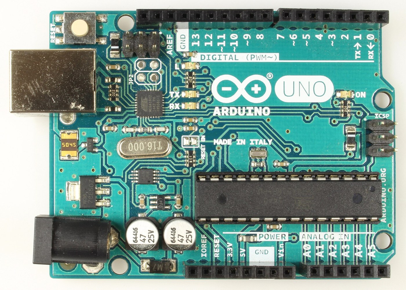


Arduino Uno R3: Assembled from Arduino's Open UNO-TH Rev3e Design Files and Flashed over ICSP
Mga Tagubilin
Get the bare board
Get the bare board
Mga materyales para sa hakbang na ito:
 Printed circuit board (PCB)1 UNO-TH Rev3e layout
Mga kailangang kasangkapan:
 Lupang Pampalaki
Fit the small surface-mount parts
Fit the small surface-mount parts
Mga materyales para sa hakbang na ito:
 Chip resistor array4 RN1-RN4
 Chip resistor2 1M
 Ceramic chip capacitor11 7x100n, 2x1u, 2x22p
 Chip varistor2 Z1, Z2
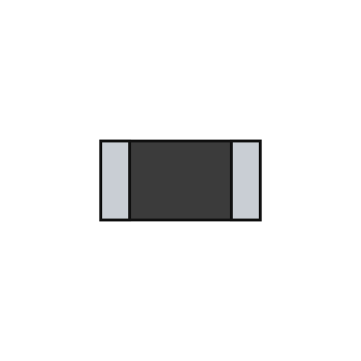 Ferrite bead1 L1
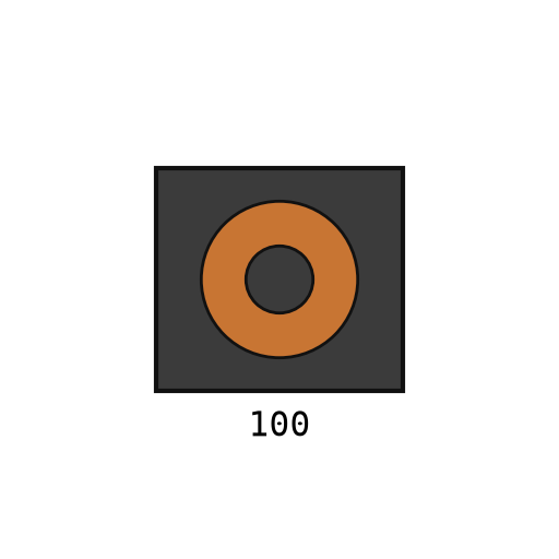 Surface-mount inductor1 L2
 Surface-mount diode2 D2, D3
 Chip LED4 1 green, 3 yellow
 Kawad na Panghinang1 a little
Mga kailangang kasangkapan:
 Flux
 Sipit na matulis ang dulo
 Istasyon ng pagkumpuni sa mainit na hangin
 PanghinangLupang Pampalaki
Fit the power and chip parts
Fit the power and chip parts
Mga materyales para sa hakbang na ito:
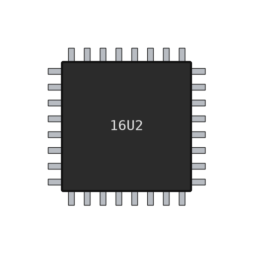 ATmega16U2 microcontroller1 U3
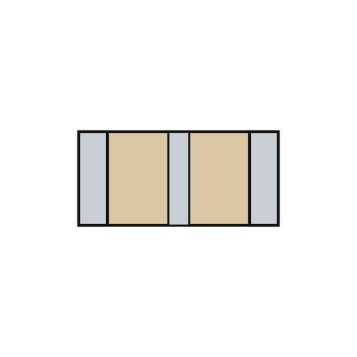 Piezoelectric ceramic resonator1 Y2
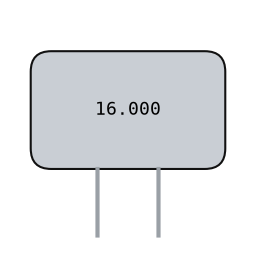 Quartz crystal1 Y1
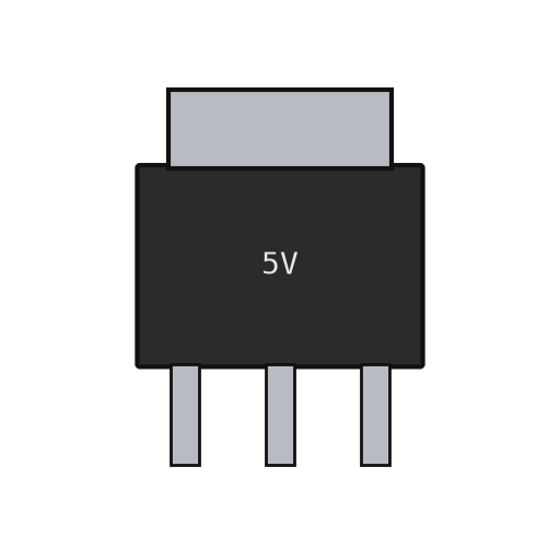 Linear voltage regulator2 U1 5 V, U2 3.3 V
 IC na operasyonal na amplipikador1 U5 LMV358
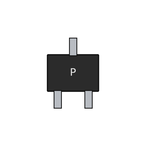 P-channel MOSFET1 T1Surface-mount diode1 D1 M7
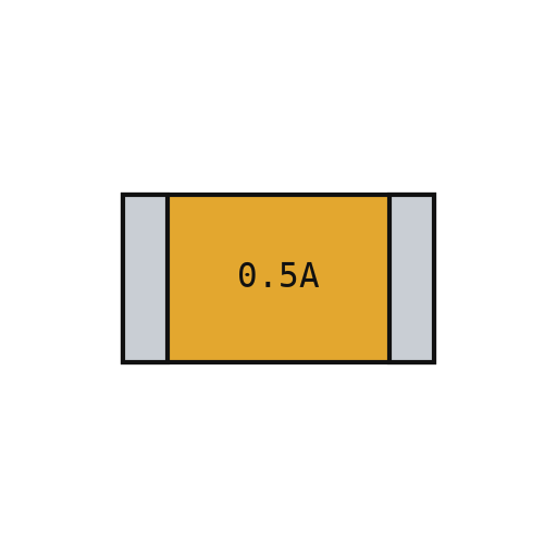 Resettable fuse1 F1
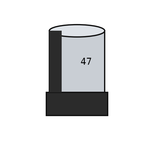 Polarised chip capacitor2 PC1, PC2Kawad na Panghinang1 a little
Mga kailangang kasangkapan:
FluxSipit na matulis ang duloIstasyon ng pagkumpuni sa mainit na hanginPanghinangLupang PampalakiFit the through-hole parts
Fit the through-hole parts
Mga materyales para sa hakbang na ito:
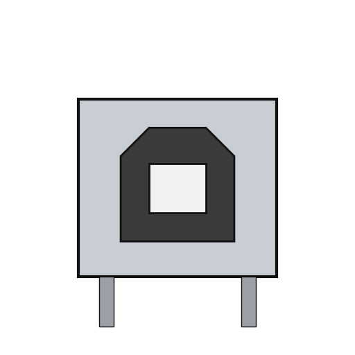 USB-B socket1 X2
 Barrel na saksakan ng kuryente1 X1
 Pindutan1 RESET
 Pin header6 10x1, 2x 8x1, 6x1 female; 2x 3x2 ICSP
 ATmega328P microcontroller1 ZU4Kawad na Panghinang1 as needed
Mga kailangang kasangkapan:
PanghinangFlash and check
Flash and check
Mga materyales para sa hakbang na ito:
 Arduino Uno firmware1 download
Mga kailangang kasangkapan:
 Multimetro
 AVR ISP programmer
 Kableng USB-B
The blink test
The blink test
Mga kailangang kasangkapan:
Kableng USB-BMga Materyales
24- 1 UNO-TH Rev3e layoutPlaceholder
- 4 RN1-RN4Placeholder
- 2 1MPlaceholder
- 11 7x100n, 2x1u, 2x22pPlaceholder
- 2 Z1, Z2Placeholder
- 1 L1Placeholder
- Placeholder
- 1 D1 M7Placeholder
- 4 1 green, 3 yellowPlaceholder
- 1 as neededPlaceholder
- Placeholder
- Placeholder
- 1 Y1Placeholder
- 2 U1 5 V, U2 3.3 VPlaceholder
- 1 U5 LMV358Placeholder
- 1 T1Placeholder
- 1 F1Placeholder
- 2 PC1, PC2Placeholder
- 1 X2Placeholder
- Placeholder
- Placeholder
- Placeholder
- Placeholder
- 1 downloadPlaceholder
Mga Kinakailangang Kasangkapan
8- Placeholder
- Placeholder
- Placeholder
- Placeholder
- 2 vendors sell this, none ship to you yetPlaceholder
- Placeholder
- Placeholder
- 1 vendor sell this, none ship to you yetPlaceholder
Ang blueprint na ito ay gumagawa ng
Kaugnay na Blueprint
Ang mga blueprint na ito ay nagbabahagi ng kaalaman — mga teknik, materyales, o prinsipyo
CC0 Pampublikong Domain
Ang blueprint na ito ay inilabas sa ilalim ng CC0. Malaya kang kumopya, magbago, mamahagi, at gumamit nang walang pahintulot.
Suportahan ang Maker sa pamamagitan ng pagbili ng mga produkto sa kanilang Blueprint Komisyon ng Maker itinakda ng mga Vendor, o lumikha ng bagong bersyon ng Blueprint na ito at isama bilang koneksyon sa iyong Blueprint upang ibahagi ang kita.