Współpraca
SZTUKA
Piękno i dobre samopoczucie
RZEMIOSŁO
KULTURA I HISTORIA
ROZRYWKA
ŚRODOWISKO
JEDZENIE I NAPOJE
INŻYNIERIA ODWROTNA
NAUKI
LEKKOATLETYKA
TECHNOLOGIA
URZĄDZENIA DO NOSZENIA
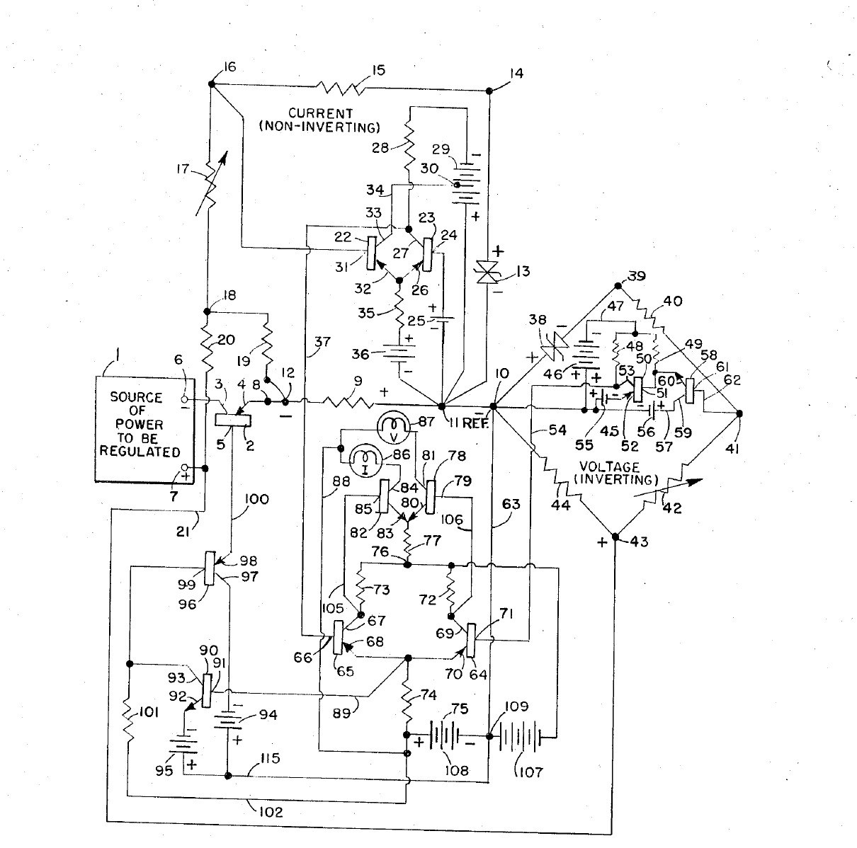


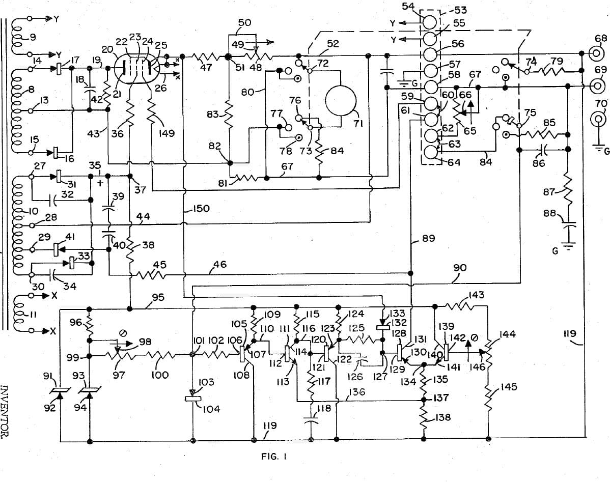
Adjustable Bench Power Supply: Constant Voltage / Constant Current with Cross-Over Lamps (Gately, Forbro, US 3,303,411, 1967)
An all-transistor bench supply with two knobs: one sets the voltage, the other the current. It holds the set voltage until the load tries to draw more than the set current, then switches at once to holding the current, and back again, with no in-between state. Two lamps show which mode is in control.
Result: an adjustable constant-voltage / constant-current DC supply with mode lamps.
Source: J. R. Gately (Forbro Design), US 3,303,411 (1967). Unknown: all component values and ratings. Builds on the same inventor's 1966 current-limited supply. Picture: the patent drawing.
Zaawansowany
Unknown
Instrukcje
1
1
Build the raw supplies
Build the raw supplies
In a case, wire the cord through a switch and fuse to two power transformers, each with rectifiers and a filter: one gives the main power to be regulated, the other the bias supplies, held steady by Zener diodes. Not given: the voltages. Ours: the case, switch and fuse.
Materiały do tego kroku:
 Obudowa aluminiowa1 sztuka
 Przewód giętki z wtyczką1 sztuka
 Przełącznik dźwigniowy1 sztuka
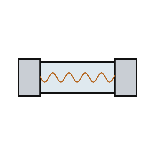 Bezpiecznik topikowy1 sztuka
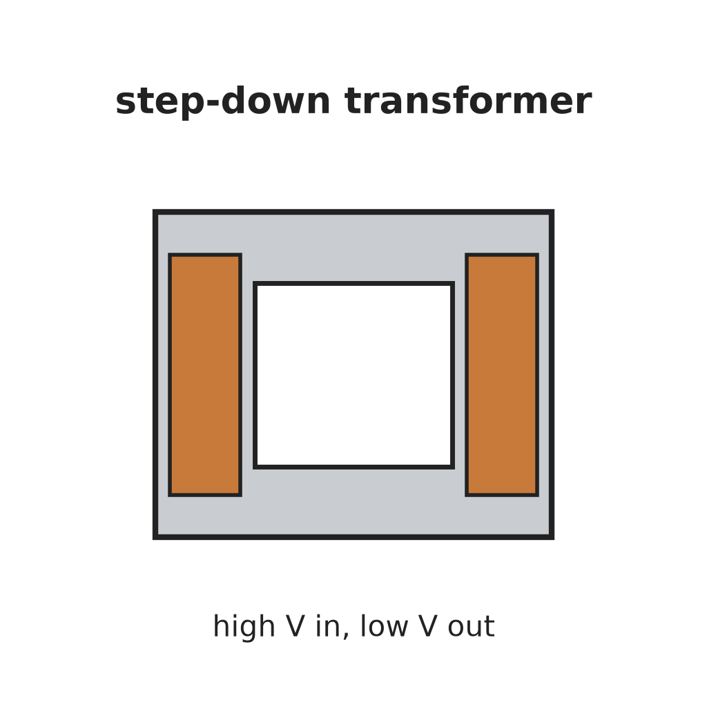 Transformator obniżający napięcie2 sztuk
 Dioda6 rectifiers
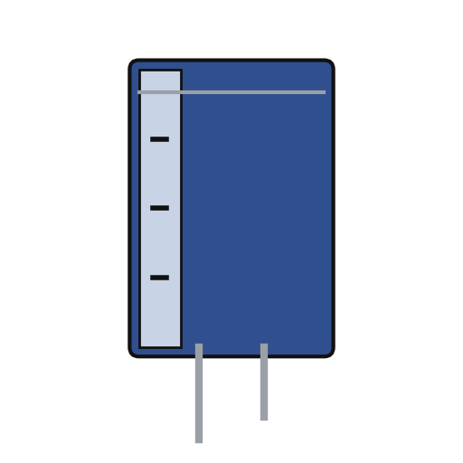 Kondensator elektrolityczny3 filters
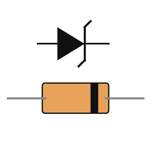 Dioda Zenera2 bias
Potrzebne narzędzia:
 Wiertarka ręczna
 Zestaw wkrętaków
2
2
Fit the pass transistor and current bridge
Fit the pass transistor and current bridge
Put a power transistor on a heat sink in series with the output: collector to the negative supply, emitter through a current-sensing resistor to the negative output terminal. Make the current bridge from the sensing resistor, a reference Zener, a reference resistor and the adjustable current-control resistor: the output current is proportional to its setting. A small trimming resistor sets the maximum current. Not given: the values.
Materiały do tego kroku:
 Tranzystor mocy1 series pass
 Radiator1 sztukaDioda Zenera1 current reference
 Reostat1 current control
 Opór elektryczny1 sensing, reference, trim set
 Zacisk bananowy2 output + and -
Potrzebne narzędzia:
 Lutownica
3
3
Build the voltage bridge
Build the voltage bridge
Make the voltage bridge from a reference Zener, a reference resistor, the adjustable voltage-control resistor and the load itself across the output. A small trimming resistor sets the maximum voltage. Add two resistors that feed the current bridge enough extra to cover the voltage bridge's own current and any voltmeter across the output, so low currents are still held exactly.
Materiały do tego kroku:
Dioda Zenera1 voltage referenceReostat1 voltage controlOpór elektryczny1 reference, trim, compensation setPotrzebne narzędzia:
Lutownica4
4
Build the amplifiers and cross-over
Build the amplifiers and cross-over
Give each bridge an error amplifier. Feed the two amplified errors to the bases of a pair of transistors sharing one emitter resistor: whichever base is the more negative takes control and cuts the other off, so the supply is always cleanly in voltage mode or current mode. Amplify the shared emitter signal through two more transistors to drive the pass transistor's base. Add an emitter-follower clamp on the bias line. Not given: the transistor types.
Materiały do tego kroku:
 Płytka drukowana1 sztuka
 Zestaw tranzystorów1 error amplifiers, cross-over pair, drivers, clampOpór elektryczny1 zestaw
 Potencjometr1 clamp divider
 Drut lutowniczy1 as needed
Potrzebne narzędzia:
Lutownica5
5
Fit the mode lamps and use it
Fit the mode lamps and use it
From the cross-over pair, drive two lamp transistors, each lighting one lamp: one for voltage mode, one for current mode. In use, set the voltage and the current limit. With a light load the voltage lamp is lit and the voltage holds; if the load tries to draw more than the set current, the supply switches to holding the current and the current lamp lights.
Materiały do tego kroku:
Zestaw tranzystorów1 two lamp drivers Oprawka żarówki2 sztuk
 Żarówka2 sztuk
Potrzebne narzędzia:
Zestaw wkrętakówMateriały
19- 1 sztukaZastępnik
- 1 sztukaZastępnik
- Zastępnik
- 1 sztukaZastępnik
- Zastępnik
- 6 rectifiersZastępnik
- 3 filtersZastępnik
- 1 voltage referenceZastępnik
- 1 series passZastępnik
- 1 sztukaZastępnik
- 1 voltage controlZastępnik
- 1 zestawZastępnik
- Zastępnik
- 1 sztukaZastępnik
- 1 two lamp driversZastępnik
- Zastępnik
- 1 as neededZastępnik
- 2 sztukZastępnik
- 2 sztukZastępnik
Według tego planu powstaje

Powiązane blueprinty
Te blueprinty dzielą się wiedzą — technikami, materiałami lub zasadami
CC0 Domena publiczna
Ten plan jest udostępniany na licencji CC0. Możesz go swobodnie kopiować, modyfikować, rozpowszechniać i wykorzystywać do dowolnych celów, bez konieczności uzyskiwania zgody.
Wesprzyj Makera kupując produkty przez jego plan, za co zarabia Prowizja Makera ustalony przez sprzedawców, lub stwórz nową iterację tego planu i dołącz go jako połączenie w swoim własnym planie, aby dzielić się przychodami.