Współpraca
SZTUKA
Piękno i dobre samopoczucie
RZEMIOSŁO
KULTURA I HISTORIA
ROZRYWKA
ŚRODOWISKO
JEDZENIE I NAPOJE
INŻYNIERIA ODWROTNA
NAUKI
LEKKOATLETYKA
TECHNOLOGIA
URZĄDZENIA DO NOSZENIA
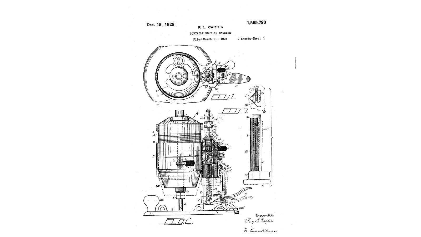


Rack-and-Pawl Plunge Router: The Motor Rides One Post on a Spring and Steps Down a Tooth at a Time (Carter, 1925)
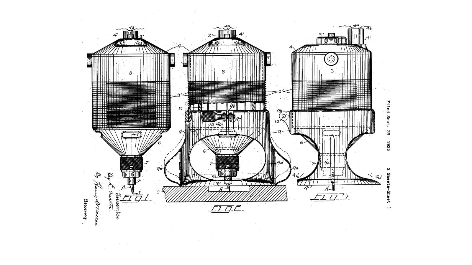
Ray L. Carter of Syracuse, New York, improved his 1924 router with US 1,565,790, dated 15 December 1925. The motor's holder now slides up and down a single strong post on a large round base, and a spring inside the post holds it up off the work. Each press of a lever moves the holder down one tooth of a rack, so a deep cavity is cut in stages. A locking pawl holds each step. Gauge nuts on a plunger stem set the final depth, and pressing the pawl's foot lets the spring lift the cutter clear.
We reuse our 1924 router's printed motor casing in a printed holder on a square steel post. The sizes are ours.
Zaawansowany
About 3 days
Instrukcje
1
1
Cutting deep in stages
Cutting deep in stages
Wczytywanie notatnika Jupyter…
2
2
Read US 1,565,790
Read US 1,565,790
"By this arrangement cavities of considerable depth may be routed by successive stages wherein each stage represents the normal depth the tool is designed to cut."
3
3
The motor and its casing come from the 1924 router
The motor and its casing come from the 1924 router
Print the casing and fit the motor, collet and switch exactly as in Carter's 1924 router; here the casing screws into a holder on a post instead of into a base.
4
4
Print the holder
Print the holder
The holder 7: a split ring threaded for the 1924 casing, clamp lugs for a thumb screw, and beside it the guide 7c with a square opening for a 1 in tube, a recess for the gib plate, two set-screw holes and the rack 17 of 3 mm teeth on its outer face. Print it rack upright. PETG, 0.2 mm layers, 40 % infill, 5 walls; no supports.
5
5
Print the base
Print the base
The base 9: a round plate 170 mm across with a 50 mm opening, and the boss 9' with a square socket for the post and a hole for its cross bolt. Print it plate down. PETG, 0.2 mm layers, 40 % infill, 5 walls; no supports.
6
6
The hollow post 8
The hollow post 8
Cut 1 inch square steel tube 200 mm long. Saw and file a slot 8b 6 mm wide and 100 mm long down the middle of one wall, starting 40 mm from the top. Push the post into the base's socket and bolt it through with an M6 bolt and lock nut. Drop a compression spring 10 into the post, then a plunger 13: a block of flat bar that slides in the tube, tapped M6 on its back for the screw that runs in the slot, with an M6 rod 13' standing up from it. Screw a flat-bar cap 12 across the post's top with a hole for the rod, and run two gauge nuts 14, 14' onto the rod above it.
Materiały do tego kroku:
 Mild Steel Square Tube 1" x 1"1 sztuka
 Płaskownik ze stali miękkiej1 sztuka
 Zestaw sprężyn naciskowych1 sztuka
 Pręt gwintowany1 sztuka
 Nakrętka sześciokątna2 sztuk
 Zestaw śrub sześciokątnych3 sztuk
 Nakrętka samohamowna z wkładką nylonową1 sztuka
Potrzebne narzędzia:
 Piła do metalu
 Zestaw pilników
 Imadło warsztatowe
 Wiertarka stołowa
 Zestaw wierteł
 Zestaw do gwintowania
 Pokrętło do gwintowników
 Klucz nastawny
 Okulary ochronne
7
7
Holder on the post
Holder on the post
Print the holder and base. Lay a strip of flat bar in the guide's recess 15 as the gib plate 15' and run two M5 set screws 16 against it, one with a wing nut on its head to lock the holder by hand. Slide the guide down over the post and fix it to the plunger with an M6 screw through the slot. Set the screws so the holder slides freely without rattling. Screw the 1924 motor casing into the holder and lock it with an M5 screw and wing nut through the lugs.
Materiały do tego kroku:
 Filament PETG1 sztukaPłaskownik ze stali miękkiej1 sztuka
 Wkręt dociskowy z końcówką wklęsłą2 sztuk
 Nakrętka skrzydełkowa2 sztuk
 Śruba z łbem walcowym na imbus2 sztuk
Potrzebne narzędzia:
 Drukarka 3D z filamentem (FDM)
 Gradownik
 Zestaw kluczy imbusowych
 Suwmiarka cyfrowa 6 cali
8
8
Pawls and lever
Pawls and lever
File a pawl 18 from flat bar with a hook 18' at its top to catch the rack's teeth, and a locking pawl 20 with a tooth 20' at its top and its lower end bent out as a foot 20d. Pivot the locking pawl on the base's boss with an M5 screw, held against the rack by a spring-steel leaf 20b. Pivot one end of a lever 19 on the boss and the pawl's lower end to the lever partway along, with a second leaf 20c holding the pawl to the rack. Each press of the lever's handle pulls the holder down one tooth, and the locking pawl drops in under it.
Materiały do tego kroku:
Płaskownik ze stali miękkiej2 sztuk Taśma ze stali sprężynowej1 sztukaŚruba z łbem walcowym na imbus3 sztukNakrętka samohamowna z wkładką nylonową3 sztuk
Potrzebne narzędzia:
Piła do metaluZestaw pilnikówImadło warsztatoweWiertarka stołowaZestaw wiertełKlucz nastawny9
9
Rout a deep recess
Rout a deep recess
Fit a straight bit. Set the gauge nuts so the plunger's rod stops on the cap at the depth wanted. Clamp a board, rest the base on it with the cutter clear, switch on, press the lever once and move the router across the area; press again and repeat, until the nuts stop it. Press the locking pawl's foot and the spring lifts the cutter out.
Potrzebne narzędzia:
 Zestaw frezów do frezarki
 Deska z drewna liściastego
 Ścisk stolarski listwowyOkulary ochronne
10
10
Troubleshooting
Troubleshooting
Plunge router troubleshooting.
Flow
Loading...
11
11
History and honest limits
History and honest limits
**Ray L. Carter** of Syracuse, New York, US 1,565,790, dated 15 December 1925, filed 21 March 1925, improving his US 1,514,894. He describes a holder "formed at one side with a guide portion having an angular vertical opening, for slidably mounting the holder upon a pedestal or post of substantially the same angularity", a coil spring housed in the pedestal, a ratchet rack and pawl to move the motor step by step, a locking pawl, gauge nuts, and a plate with set screws to take up wear. His post is triangular and cast; ours is 1 inch square steel tube. His holder and base are metal; ours are printed PETG. His motor ran on mains; ours is the small DC motor of our 1924 router. The sizes are ours.
Materiały
12- 1 sztukaZastępnik
- 2 sztukZastępnik
- 1 sztukaZastępnik
- 1 sztukaZastępnik
- 2 sztukZastępnik
- 3 sztukZastępnik
- Zastępnik
- 1 sztukaZastępnik
- Zastępnik
- 2 sztukZastępnik
- Zastępnik
- 1 sztukaZastępnik
Wymagane narzędzia
16- Zastępnik
- Zastępnik
- Zastępnik
- Zastępnik
- Zastępnik
- Zastępnik
- Zastępnik
- Zastępnik
- Zastępnik
- Zastępnik
- Zastępnik
- Zastępnik
- Zastępnik
- 1 vendor sell this, none ship to you yetZastępnik
- Zastępnik
- Zastępnik
Pliki projektowe
2Według tego planu powstaje

Powiązane blueprinty
Te blueprinty dzielą się wiedzą — technikami, materiałami lub zasadami
CC0 Domena publiczna
Ten plan jest udostępniany na licencji CC0. Możesz go swobodnie kopiować, modyfikować, rozpowszechniać i wykorzystywać do dowolnych celów, bez konieczności uzyskiwania zgody.
Wesprzyj Makera kupując produkty przez jego plan, za co zarabia Prowizja Makera ustalony przez sprzedawców, lub stwórz nową iterację tego planu i dołącz go jako połączenie w swoim własnym planie, aby dzielić się przychodami.