Współpraca
SZTUKA
Piękno i dobre samopoczucie
RZEMIOSŁO
KULTURA I HISTORIA
ROZRYWKA
ŚRODOWISKO
JEDZENIE I NAPOJE
INŻYNIERIA ODWROTNA
NAUKI
LEKKOATLETYKA
TECHNOLOGIA
URZĄDZENIA DO NOSZENIA
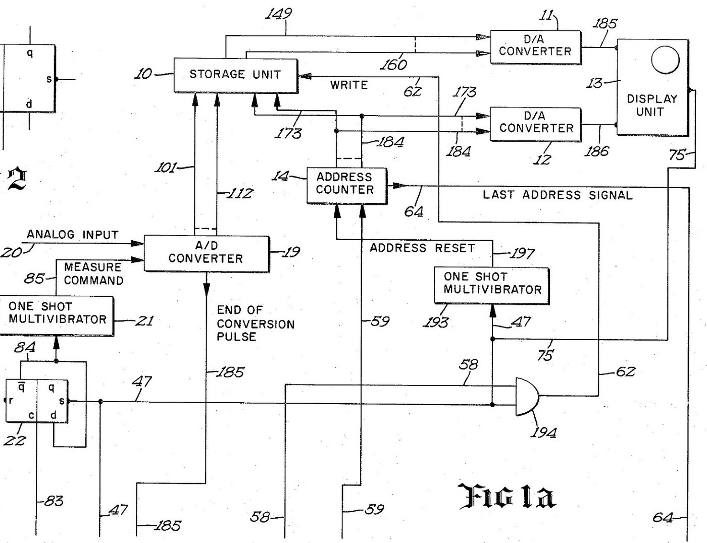


Digital Oscilloscope: Waveform Stored in Memory and Shown on a CRT (Schumann, Nicolet, US 3,816,815, 1974)
An oscilloscope with a memory. After a trigger, an analog-to-digital converter measures the input at regular intervals and writes each reading into its own memory register, replacing the old one. The screen then shows the memory: each register's number sets the beam's height, its address sets the beam's place across. The last waveform can be held on the screen as long as you like.
Result: a digital storage oscilloscope with 4,096 points of 12 bits, refresh and hold modes and single-shot capture.
Source: R. W. Schumann (Nicolet), US 3,816,815 (1974). Unknown: sample rate, bandwidth, voltages and the parts used. Picture: the patent drawing.
Ekspert
Unknown
Instrukcje
1
1
Sample and convert the input
Sample and convert the input
Bring the analog input to an analog-to-digital converter, through a BNC socket. A sampling oscillator, divided by four by two flip-flops so the first reading comes soon after the sweep starts, fires a one-shot multivibrator that gives the converter its measure command. The converter holds each 12-bit result on its output lines and signals the end of each conversion. Ours: a BNC socket. Not given: the sample rate.
Materiały do tego kroku:
 Przetwornik analogowo-cyfrowy1 12-bit converter
 Generator zegarowy1 sampling oscillator
 Zestaw układów logicznych1 flip-flops, one-shots, gates
 Zestaw złączy współosiowych (BNC / SO-239)1 input socket
Potrzebne narzędzia:
 Lutownica
 Ściągacz izolacji
2
2
Store each reading in memory
Store each reading in memory
Wire an integrated-circuit memory of 4,096 registers, 12 bits each, that can be read without changing it. A 12-bit address counter picks the register. On each write command the register at the current address takes the last reading from the converter, and the counter steps on. When the sweep starts, a one-shot resets the counter to zero. When it reaches the last address, its last-address signal ends the sweep.
Materiały do tego kroku:
 Pamięć półprzewodnikowa1 4,096 x 12-bit store
Potrzebne narzędzia:
LutownicaŚciągacz izolacji3
3
Drive the CRT from the memory
Drive the CRT from the memory
Feed the addressed register's number to one digital-to-analog converter and the address to a second. Their outputs drive the vertical and horizontal deflection plates of a cathode-ray tube, so the beam always stands at the height of the stored reading and at the place of its address. Wire the sweep line to the tube's intensifier, to brighten the trace while a waveform is being taken.
Materiały do tego kroku:
 Przetwornik cyfrowo-analogowy2 vertical and horizontal
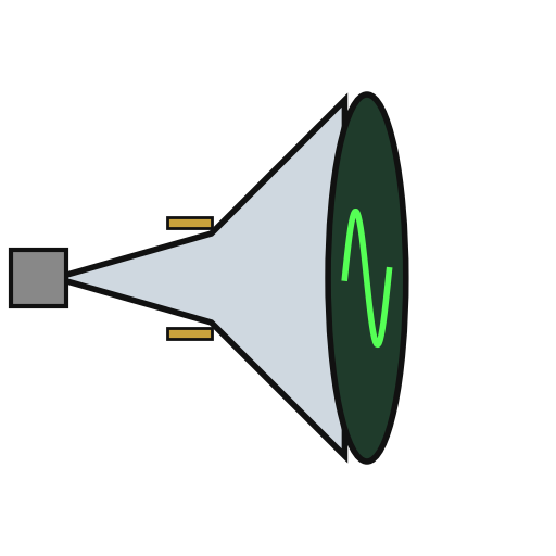 Kineskop1 display tube
Potrzebne narzędzia:
LutownicaŚciągacz izolacji4
4
Wire the trigger and the modes
Wire the trigger and the modes
A trigger input, usually from the leading edge of the input waveform, starts the sweep, once a measure flip-flop has armed it. Put a two-position mode switch on the face: MODE I and MODE II. Add a push button in the probe, a switch on the panel and an external initiate input; each goes through a flip-flop that removes contact bounce. Two more oscillators step the memory round to refresh the display between waveforms. Mount it all in a case with its supply. Ours: toggle switches, an aluminium case, a DC supply. Not given: the supply voltages.
Materiały do tego kroku:
Generator zegarowy2 display sequencing oscillators Przełącznik dźwigniowy2 mode and panel switches
 Przycisk1 probe switch
 Obudowa aluminiowa1 case
Potrzebne narzędzia:
 Zasilacz prądu stałego
 Wiertarka stołowaLutownica
5
5
Capture and hold a waveform
Capture and hold a waveform
In MODE I, refresh: each new triggered waveform replaces the last on the screen. Press the probe or panel switch to hold: new waveforms are rejected and the last one stays on the screen. In MODE II the screen normally holds; on command, it takes the first waveform after the command, stores it and shows it steadily. Test it with a known signal.
Potrzebne narzędzia:
 Generator funkcyjny
Materiały
10- 1 12-bit converterZastępnik
- 2 display sequencing oscillatorsZastępnik
- 1 flip-flops, one-shots, gatesZastępnik
- 1 input socketZastępnik
- 1 4,096 x 12-bit storeZastępnik
- 2 vertical and horizontalZastępnik
- 1 display tubeZastępnik
- Zastępnik
- Zastępnik
- 1 caseZastępnik
Według tego planu powstaje

Powiązane blueprinty
Te blueprinty dzielą się wiedzą — technikami, materiałami lub zasadami
CC0 Domena publiczna
Ten plan jest udostępniany na licencji CC0. Możesz go swobodnie kopiować, modyfikować, rozpowszechniać i wykorzystywać do dowolnych celów, bez konieczności uzyskiwania zgody.
Wesprzyj Makera kupując produkty przez jego plan, za co zarabia Prowizja Makera ustalony przez sprzedawców, lub stwórz nową iterację tego planu i dołącz go jako połączenie w swoim własnym planie, aby dzielić się przychodami.