
The Induction Coil
A battery supplies a steady low voltage. A great many useful things — a spark, an X-ray tube, a radio transmitter — need a high one. There is no way to get it by connecting batteries, because a hundred cells in series is a hundred cells to buy, maintain and carry.
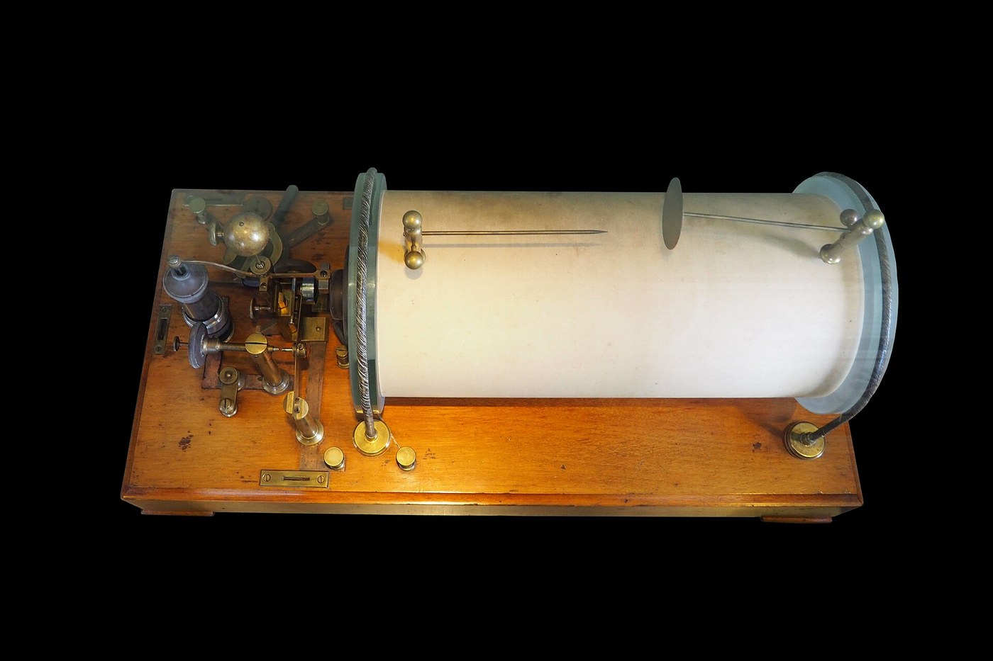
The induction coil takes the voltage it needs from a place that costs nothing: the rate at which a magnetic field changes.
Two windings share an iron core — a few turns of thick wire, and many thousands of turns of fine wire. A current in the primary magnetises the core. Nothing happens while it is steady. But interrupt it, and the collapsing field induces a voltage in the secondary that is larger by roughly the turns ratio — and, far more importantly, larger still because the collapse is violently fast.
That is the part that surprises people. The turns ratio might be 1:100, and the output can be thousands of times the input, because induced voltage depends on how quickly the field changes, not merely on how much it changes. A slow collapse gives nothing; an abrupt one gives a spark.
So the design problem is not really the winding. It is the interrupter — the thing whose whole job is to break the primary circuit as suddenly as possible, again and again — and the capacitor across it that stops the break being softened by its own arc.
Instrukcje
Confirm that steady current does nothing at all
Confirm that steady current does nothing at all
Wind a primary of a few dozen turns and a secondary of several hundred on the same iron core, and connect a sensitive meter across the secondary.
Switch the primary on and leave it on. Watch the meter.
Expect a flick at the moment of switching and then nothing, however long you wait and however large the current.
Write the conclusion plainly, because everything else follows from it: a magnetic field does not induce a voltage. A CHANGING magnetic field does. A steady current is, to the secondary, indistinguishable from no current.
Materiały do tego kroku:
 Drut miedziany emaliowany50 m
 Drut stalowy ocynkowany2 m
Potrzebne narzędzia:
 Multimetr analogowy
Compare making the circuit with breaking it
Compare making the circuit with breaking it
Switch the primary on and off repeatedly and watch the secondary carefully at each event.
Expect the break to give a much bigger kick than the make.
The reason is asymmetry in time, not in the coil. Closing a switch builds the field at a rate the circuit's own inductance limits; opening one collapses it as fast as the contacts can separate, which is far faster.
This is why every induction coil is designed around the interruption and not the connection, and why the output is a series of sharp pulses rather than anything resembling the smooth supply that drives it.
Build the interrupter and make it break itself
Build the interrupter and make it break itself
Arrange a springy contact so that the primary current, flowing through the electromagnet, pulls the contact open — which cuts the current, which releases the contact, which closes it again.
Expect a buzz and a rapid train of output pulses.
You have built an oscillator out of nothing but a switch that turns itself off, and it is exactly the arrangement in an electric bell.
Note the elegance and the flaw together: it needs no separate timing device, and its rate is set by whatever the spring and the magnet happen to agree on, which is a poor way to control anything.
Find out what the capacitor is really for
Find out what the capacitor is really for
Run the coil and watch the interrupter contacts closely. Then connect a capacitor across them and compare.
Expect a visible arc and pitted contacts without it, a much sharper break and a bigger output with it.
The reason is worth stating carefully. An arc is the current refusing to stop — it keeps flowing through ionised air after the metal has parted, so the field collapses slowly and the output is feeble. The capacitor gives that current somewhere to go for the microseconds it needs, so the arc never strikes.
It is not a smoothing component here. It is there to make an event sharper, which is nearly the opposite of what capacitors usually do.
Test whether turns ratio predicts the output
Test whether turns ratio predicts the output
Measure the output spark gap you can sustain, then compute the turns ratio and the voltage it predicts.
Expect the real output to exceed the turns-ratio prediction, substantially.
Then slow the interrupter deliberately — soften the break with a poor contact — and watch the output fall even though the turns are unchanged.
The transformer rule is a statement about steady alternating current. An induction coil is not run that way, so its output is governed by the speed of one violent transient. The winding sets the scale; the interrupter sets the answer.
Treat the output as dangerous even from a small battery: it is the voltage, not the source, that jumps a gap.
History & Context
History & Context
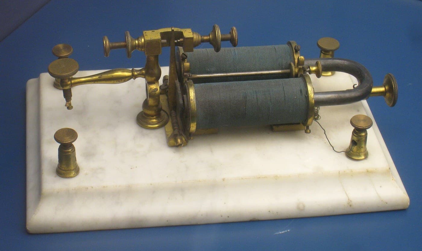
The idea is Faraday's; the instrument is a chain of improvers. Nicholas Callan, a priest and physicist at Maynooth, built large coils from the 1830s. Heinrich Ruhmkorff, an instrument maker in Paris, refined the construction and insulation around 1851 to the point where the coil became a reliable laboratory product — which is why it is usually called a Ruhmkorff coil even though he was not first. Making a thing manufacturable is a real contribution, and it is the one most often mistaken for invention.
It was the standard high-voltage source for half a century. Every X-ray tube, every gas-discharge experiment, every spark-gap radio transmitter — including the one in the Marconi Wireless blueprint — ran on one. Röntgen discovered X-rays using a coil in 1895, so this device is upstream of a whole branch of medicine as well as of radio.
The interrupter was the weak point, and the history is a hunt for better ones. The self-buzzing contact wears out and limits the rate; mercury turbine interrupters, electrolytic Wehnelt interrupters and motor-driven breakers were all attempts at the same problem — break the current faster, more often, and without destroying yourself. That is the same requirement as a switching power supply's transistor today, and the modern answer is the same trick with no moving parts.
It is the ignition coil in a petrol engine. Unchanged in principle: low-voltage supply, two windings, an interrupter (contact breaker, later a transistor), a capacitor across it to stop arcing, and a spark at the output. A component invented for the laboratory bench ended up in several billion vehicles doing precisely the job it was invented to do.
Honest limits. It produces sharp unidirectional pulses, not a controllable waveform, so it is a poor supply for anything that wants steady high voltage. Output depends on the interrupter's behaviour, which drifts as contacts wear. Insulation is the real engineering difficulty — thousands of adjacent turns at thousands of volts want to arc between layers, which is why the secondary is wound in sections. And the sharp break radiates broadband interference in every direction, which is delightful if you are building a spark transmitter and intolerable for everybody else.
Materiały
2- Zastępnik
- Zastępnik
Wymagane narzędzia
1- Zastępnik
Materiały z połączonych planów

Powiązane blueprinty
Te blueprinty dzielą się wiedzą — technikami, materiałami lub zasadami


CC0 Domena publiczna
Ten plan jest udostępniany na licencji CC0. Możesz go swobodnie kopiować, modyfikować, rozpowszechniać i wykorzystywać do dowolnych celów, bez konieczności uzyskiwania zgody.
Wesprzyj Makera kupując produkty przez jego plan, za co zarabia Prowizja Makera ustalony przez sprzedawców, lub stwórz nową iterację tego planu i dołącz go jako połączenie w swoim własnym planie, aby dzielić się przychodami.