Współpraca
SZTUKA
Piękno i dobre samopoczucie
RZEMIOSŁO
KULTURA I HISTORIA
ROZRYWKA
ŚRODOWISKO
JEDZENIE I NAPOJE
INŻYNIERIA ODWROTNA
NAUKI
LEKKOATLETYKA
TECHNOLOGIA
URZĄDZENIA DO NOSZENIA
Sprung-Leg Tubing Cutter: a Bent Rod With a Disk Outside and a Roller Inside, the Handle's Screw Bends One Leg In (Zeiler, 1958)
Forge

Autor

Forge

13. listopad 2026NO
8
0
0
0
0

Sprung-Leg Tubing Cutter: a Bent Rod With a Disk Outside and a Roller Inside, the Handle's Screw Bends One Leg In (Zeiler, 1958)

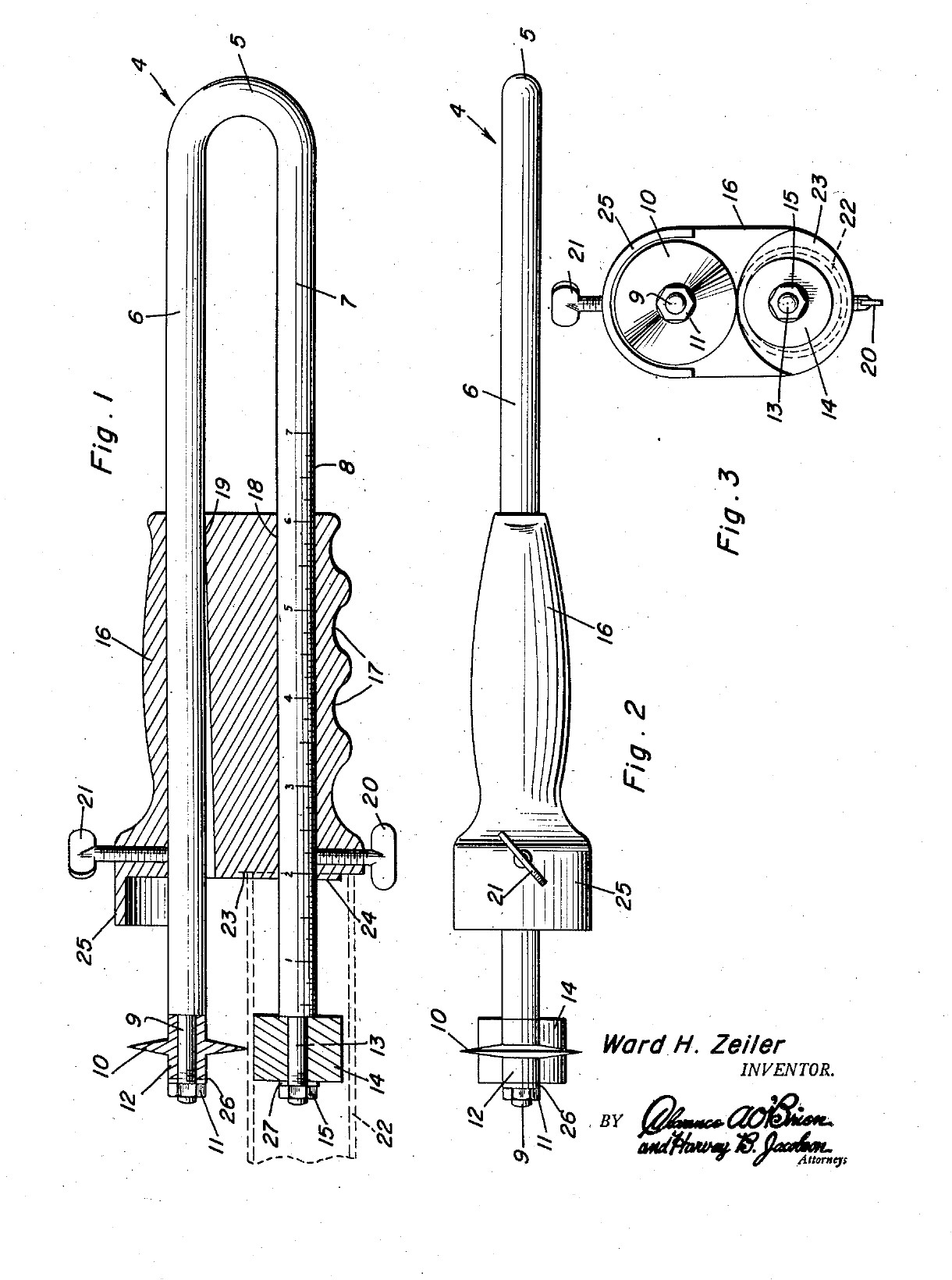
Ward H. Zeiler of Holyoke, Colorado, received US 2,821,781, dated 4 February 1958, for a plumber's tubing cutter that cuts a tube square, to length, near its end. The frame is one springy rod bent into a U. The lower leg goes into the tube and carries a roller. The upper leg carries a cutting disk outside the tube. A handle slides along both legs. Its front end stops against the tube end, so the cut length is read off a scale on the lower leg. A screw in the handle bends the upper leg in and presses the disk onto the tube, and turning the tool cuts it off. All sizes are ours.
Średniozaawansowany
About 2 days

Instrukcje

1

Why the frame must spring

Wczytywanie notatnika Jupyter…
2

Read US 2,821,781

"The leg 7 is then inserted in the tube 22 and the roller 14 and the projection 24 are engaged in the upper portion of said tube. The screw 21 is then tightened for bending the leg 6 of the frame 4, thus engaging the knife 10 with the periphery of the tube 22."
3

Print the template

The bent frame, its ends, the disk, roller and handle at 1:1, with the oval bore, the screws and the scale. print at 100 % (check the 50 mm bar).
Plik projektowyPDFCC0 - Free
4

Bend the frame

Cut 470 mm of 6 mm spring steel wire. Heat the middle 40 mm red with the torch and bend it round a 10 mm bar into a U with the legs 16 mm apart, and straighten the legs parallel. Heat the last 25 mm of each leg red and let it cool slowly in the dying forge, so the ends are soft enough to file and thread. Leave the rest of the legs as they are: they must spring.

Materiały do tego kroku:

Drut sprężynowyDrut sprężynowy1 sztuka

Potrzebne narzędzia:
Palnik do lutowania twardegoPalnik do lutowania twardego
Palenisko kowalskiePalenisko kowalskie
Kleszcze kowalskieKleszcze kowalskie
Imadło warsztatoweImadło warsztatowe
Młotek ślusarski z kulistym rąbemMłotek ślusarski z kulistym rąbem
Piła do metaluPiła do metalu
Rękawice spawalniczeRękawice spawalnicze
Okulary ochronneOkulary ochronne
5

Thread the leg ends

Turn or file the last 24 mm of each leg to 5 mm, leaving a square shoulder, and cut an M5 thread on the last 8 mm with the die.

Potrzebne narzędzia:

Tokarka do metaluTokarka do metalu
Uchwyt tokarski 3-szczękowyUchwyt tokarski 3-szczękowy
Nóż tokarskiNóż tokarski
Zestaw pilnikówZestaw pilników
Zestaw do gwintowaniaZestaw do gwintowania
Suwmiarka cyfrowa 6 caliSuwmiarka cyfrowa 6 cali
Olej do cięciaOlej do cięcia
6

Turn the disk and the roller

Disk: chuck a tool steel bar, turn 12 mm of it to 18 mm, drill it 5 mm, and turn the front 6 mm to a 50 degree edge, sharp in its middle. Turn the next 4 mm down to a 10 mm hub and part it off. Roller: turn 10 mm mild steel bar 16 mm long and drill it 5.2 mm, so it spins freely on the leg.

Materiały do tego kroku:

Pręt ze stali narzędziowejPręt ze stali narzędziowej1 sztuka
Pręt okrągły ze stali niskowęglowejPręt okrągły ze stali niskowęglowej1 sztuka

Potrzebne narzędzia:

Tokarka do metaluTokarka do metalu
Uchwyt tokarski 3-szczękowyUchwyt tokarski 3-szczękowy
Nóż tokarskiNóż tokarski
Przecinak tokarskiPrzecinak tokarski
Zestaw nawiertakówZestaw nawiertaków
Zestaw wiertełZestaw wierteł
Suwmiarka cyfrowa 6 caliSuwmiarka cyfrowa 6 cali
Okulary ochronneOkulary ochronne
7

Harden and temper

Heat the disk to a cherry red, until a magnet no longer sticks, and quench it in water, moving it about. Rub it bright with a stone, warm it on a piece of steel plate over the fire, and quench again as soon as it turns a light straw colour.

Potrzebne narzędzia:

Palenisko kowalskiePalenisko kowalskie
Kleszcze kowalskieKleszcze kowalskie
Mały magnesMały magnes
Kadź hartowniczaKadź hartownicza
WodaWoda
OsełkaOsełka
Rękawice spawalniczeRękawice spawalnicze
Okulary ochronneOkulary ochronne
8

Make the handle

Saw 90 mm of 32 mm aluminium bar and face the ends. Drill two 6.2 mm holes through it lengthways, 16 mm apart, each 8 mm off the centre. With a round file, open the front 70 mm of the upper hole towards the lower one, 1.8 mm at the front face, tapering to nothing. Drill and tap M6 into the upper hole from the top, 12 mm from the front, and into the lower hole from below, 14 mm from the front. Saw and file away the lower half of the front 8 mm, leaving a 10 mm round boss round the lower hole. File three finger grooves underneath.

Materiały do tego kroku:

Pręt aluminiowy okrągłyPręt aluminiowy okrągły1 sztuka

Potrzebne narzędzia:

Piła do metaluPiła do metalu
Tokarka do metaluTokarka do metalu
Uchwyt tokarski 3-szczękowyUchwyt tokarski 3-szczękowy
Wiertarka stołowaWiertarka stołowa
Imadło maszynoweImadło maszynowe
Zestaw wiertełZestaw wierteł
Zestaw do gwintowaniaZestaw do gwintowania
Zestaw pilnikówZestaw pilników
Zestaw pilników iglakówZestaw pilników iglaków
Suwmiarka cyfrowa 6 caliSuwmiarka cyfrowa 6 cali
9

Make the guard

Cut a strip of brass sheet 12 mm wide and 50 mm long, bend it into a half round hood that reaches 12 mm past the handle's front over the disk, and fix its back end on top of the handle with two small screws.

Materiały do tego kroku:

Blacha mosiężnaBlacha mosiężna1 sztuka
Śruba z łbem walcowym na imbusŚruba z łbem walcowym na imbus2 sztuk

Potrzebne narzędzia:

Piła do metaluPiła do metalu
Zestaw pilnikówZestaw pilników
Wiertarka stołowaWiertarka stołowa
Zestaw wiertełZestaw wierteł
Zestaw do gwintowaniaZestaw do gwintowania
Imadło warsztatoweImadło warsztatowe
10

Assemble

Slide the handle onto the legs from the open end, the upper leg in the oval bore. Put the disk on the upper leg's end, hub outwards, then a washer and an M5 nut, snug enough that the disk still turns. Fit the roller the same way on the lower leg. Screw in the M6 feed screw on top and the setscrew below.

Materiały do tego kroku:

Podkładka płaskaPodkładka płaska2 sztuk
Nakrętka sześciokątnaNakrętka sześciokątna2 sztuk
Śruba z łbem walcowym na imbusŚruba z łbem walcowym na imbus1 sztuka
Wkręt dociskowy z końcówką wklęsłąWkręt dociskowy z końcówką wklęsłą1 sztuka

Potrzebne narzędzia:
Klucz nastawnyKlucz nastawny
Zestaw kluczy imbusowychZestaw kluczy imbusowych
11

Mark the scale

Slide the handle so its recess face is 20 mm from the disk's edge and lock it. File a nick across the lower leg at the handle's back face and mark it 20. File a nick every 10 mm towards the bend, deeper every 50 mm. The handle's back face now reads the cut length.

Potrzebne narzędzia:

Zestaw pilników iglakówZestaw pilników iglaków
Suwmiarka cyfrowa 6 caliSuwmiarka cyfrowa 6 cali
12

Cut a tube to length

Set the handle to the length you want and lock the setscrew. Push the lower leg into the tube until the end bears in the recess, with the roller and boss against the inside. Tighten the feed screw until the disk touches. Turn the tool round the tube, giving the screw a little more each turn, until the end drops off. Clean the cut with a deburring tool.

Materiały do tego kroku:

Rura miedzianaRura miedziana1 sztuka

Potrzebne narzędzia:

Imadło warsztatoweImadło warsztatowe

GradownikGradownik
Zestaw kluczy imbusowychZestaw kluczy imbusowych
Suwmiarka cyfrowa 6 caliSuwmiarka cyfrowa 6 cali
13

Troubleshooting

Sprung-leg tubing cutter troubleshooting.

Flow

Loading...
14

History and honest limits

**Ward H. Zeiler** of Holyoke, Colorado, US 2,821,781, dated 4 February 1958, filed 23 November 1956. He claimed "a substantially U-shaped resilient frame including legs extending slidably through the bores" and "a feed screw ... for bending said one leg within the confines of the handle for engaging the cutting disk with the tube". His frame was "suitable resilient metal"; ours is spring steel wire. His handle was a metal sleeve with a guard formed on it; ours is aluminium bar with a brass guard. The patent gives no sizes; all of ours are ours.

Materiały

10

Wymagane narzędzia

28

Pliki projektowe

1

Według tego planu powstaje

CC0 Domena publiczna

Ten plan jest udostępniany na licencji CC0. Możesz go swobodnie kopiować, modyfikować, rozpowszechniać i wykorzystywać do dowolnych celów, bez konieczności uzyskiwania zgody.

Wesprzyj Makera kupując produkty przez jego plan, za co zarabia Prowizja Makera ustalony przez sprzedawców, lub stwórz nową iterację tego planu i dołącz go jako połączenie w swoim własnym planie, aby dzielić się przychodami.

Dyskusja

(0)

Zaloguj się aby dołączyć do dyskusji

Ładowanie komentarzy...